
A Three-Piece Toolset to Minimize Metal Additive Build Failures (Includes Video)
Three separate software tools from Siemens attempt to control some of the most challenging variables within metal AM: build orientation, distortion and deposition paths. Part of software video series.


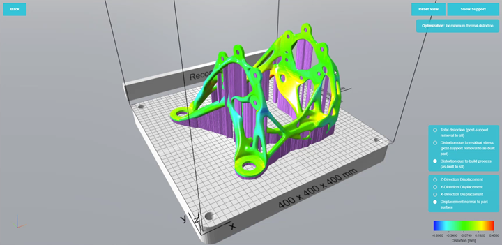
Siemens’ Sunata software optimizes build orientation for minimum thermal distortion while allowing the user to designate any areas where support structures should be avoided.
Despite all recent and ongoing technological advancements within additive manufacturing (AM), trial-and-error still plays an outsized role in achieving the desired characteristics and tolerances of a part — especially the first time that part is printed. The reason why, especially when it comes to metal powder bed fusion, is as complex as the variables that must be accounted for during the build process. To bring these variables under control, AM designers and engineers will need more robust tools that steer the user toward choosing optimal parameters for build orientation, support structures, distortion and deposition paths.
Siemens is attempting to resolve these larger issues through a series of software simulation tools that the company likens to three legs of a stool. The triple toolset was set in motion last November when Siemens acquired Atlas 3D, an Indiana-based software developer focused on the direct metal laser sintering (DMLS) process. The company’s premier software package called Sunata, which now resides with Siemens, aims to provide engineers with a level of automation for determining optimal print orientation and support structures for additive parts.


“There's this large issue in the industry right now where people are struggling to get prints right, especially early in their additive adoption,” says Ashley Eckhoff, a software programmer and marketing manager for Siemens Digital Industries Software. “And there's a long learning process that these customers go through, consistently gaining more knowledge about how their particular machines and various materials work, and they're trying to distill all of that down into a series of processes that increase the odds of getting the quality print.”
Sticking with the three-legged stool analogy, the first leg, according to Siemens, provides about 80% of the stool’s overall support.
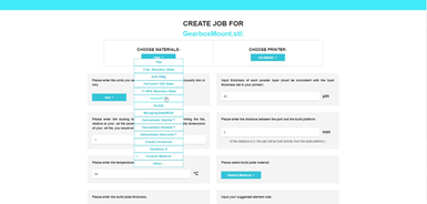
Sunata presents a simplified menu for the selection of several build variables, including material, printer model, build plate thickness, and the thickness of each powder layer.
In other words, the company says that Sunata — its cloud-based, CAD-agnostic solution to optimize build orientation and support structures — can get its users about 80% of the way to “right first time” printing.
Chad Barden, former Atlas 3D CEO and now a product portfolio lead for Siemens, said that Atlas 3D began trying to solve the right-first-time printing dilemma by taking deep dives into scan patterns and laser power management. This field of research was helpful toward minimizing distortion and improving build success. However, relative to choosing the right orientation for the part, these variables represented only 10% to 15% solutions. “Meaning, you could solve 10% to 15% of the problems with those approaches,” Barden says. “But choosing the right orientation, that was an 80% or 90% solution.”
Sunata attempts to simulate the powder bed fusion build process with computationally efficient models of the thermal effects taking place inside the build chamber. Barden says that this includes both the immediate mechanical effects from the build process as well as effects result from residual stresses that emerge within the part while it’s heating and cooling. Barden’s team realized that with enough efficiency built into these models, the software could intelligently pinpoint the optimal orientation that minimizes distortion from residual stress during the build process.
Barden says that the software also uses heuristic algorithms that allow the user to minimize build time, support volume, and post-processing efforts. “But at the end of the day, our core capability is to improve the rate of success of prints by helping an engineer choose the exact right orientation, and by automatically generating the support structures that are necessary for that orientation,” he says. “It takes the guesswork out of the out of the metal additive process.”
The Distortion Map
Using all of the knowledge the software has gained about potential distortion within a part, it generates a compensated model with a slightly altered part geometry designed to minimize overheating.
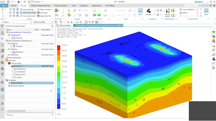
In the video below, I interviewed Ashley Eckhoff about the Simcenter 3D AM Process Simulation tool — the second leg of the stool. Eckhoff says that Simcenter performs a holistic analysis of everything within the build tray, including the residual powder, so that the entirety of the thermal map can be considered before printing. In Simcenter, the user selects the material, the printer, and various characteristics desired for the part. The software then divides the part in macro layers composed of dozens or hundreds of actual print layers grouped together depending on the desired resolution. As the print process is simulated, the system looks for residual heat within the different layers as well as within the residual powder that surrounds the part during the print process. Finally, the software applies a finite element analysis (FEA) mesh across the part and the support structures, as well as the residual powder inside the build tray.
Eckhoff says that the result of this analysis is a map of the total distortion within the part. “You can have the distortion after the print while it's still in the build tray, or the distortion after it's been removed from the build tray.
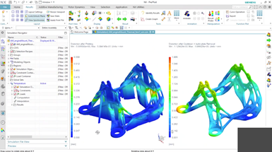
A side-by-side comparison of within Simcenter of the distortion level of a part after printing and after cooldown and build-plate removal.
And each of these gives you a slightly different view about what's happening during the printing process,” Eckhoff says. At the end of the process, the software creates what Eckhoff calls a compensated model that takes into account everything the software has learned about the thermal stresses and strains that were created from the thermal buildup during the printing process, and creates a model that compensates for those heat buildups by suggesting a new part geometry that won’t cause distortion during the print process.
Skill Level: Expert
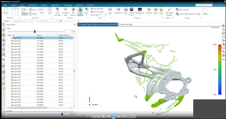
The green colors represent the deposition path with a metal powder bed fusion 3D printer. The software can simulate how these deposition paths might produce overheating and distortion.
The third leg of the stool is a much more granular software tool that Eckhoff recommends only for expert AM users. The NX AM Path Optimizer tool analyzes how the deposition path can produce localized areas of overheating within a part, which causes distortion. Eckhoff says that the NX software can adjust the deposition path to compensate for any areas where local distortion might occur, then pass the adjusted tool path to the machine to minimize any localized overheating areas issues.
For example, when a part is sliced into layers for printing, within each slice is a deposition path that essentially provides the machine with a path for how the laser will travel while sintering the material.
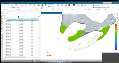
Siemens NX AM Path Optimizer shows the crosshatches, lines, and other linear shapes that represent the deposition path of an AM part. These paths can be adjusted to minimize distortion.
These paths can resemble cross-hatches, lines, and other linear shapes that, depending on other variables like laser power and speed, each affect potential distortion within a part. The software can simulate how these deposition paths might produce overheating, which in turn can result in recoater blade collisions and distortion, or cause the part to be out of tolerance.
As the software looks through each individual layer, it identifies any distorted regions, analyzes the deposition path, and adjusts the path in a manner that minimizes distortion. Other parameter adjustments made by the software include dwell time (the duration of the laser focusing on any given spot) as well as laser power.
“When we have the machine layering down materials in a certain pattern with certain parameters, we can find areas in that deposition path that cause overheating,” Eckhoff says. “And we can address those by adjusting that deposition path or adjusting the machine parameters for a certain period during print. It’s a simulation-based tool, but it's looking at [simulation] slightly differently. It looks specifically at the deposition paths and ways we can alter those to address deformations and print problems.”
To learn more about the Simcenter 3D AM Process Simulation tool, check out my interview with Ashley Eckhoff below.


Related Content

Decentralized Manufacturing Network Aims to Make 3D Printers a Shared Global Resource
The 3DOS additive manufacturing network will let OEMs and creators take advantage of open 3D printer capacity anywhere in the world.
Read More
Additive Manufacturing Production at Scale Reveals the Technology's Next Challenges: AM Radio #28
Seemingly small issues in 3D printing are becoming larger problems that need solutions as manufacturers advance into ongoing production and higher quantities with AM. Stephanie Hendrixson and Peter Zelinski discuss 6 of these challenges on AM Radio.
Read More
Ultimaker 5.0 Cura Enables Finer, Faster Prints
The software’s enhanced slicing engine is said to enable thinner walls and finer details in additive manufacturing.
Read More
The World’s Tallest Freestanding 3D Printed Structure
Dimensional Innovations paired additive and subtractive manufacturing to create a monument for the NFL’s Las Vegas Raiders new stadium. The “never been done before” project resulted in the world’s tallest freestanding 3D printed structure.
Read MoreRead Next

Link3D Software Simplifies Additive Manufacturing Workflows
Technology from Link3D facilitates each step in the 3D printing process for companies.
Read More
UnionTech PolyDevs Software Prepares 3D Printing Data
The software is intended for use with UnionTech's Pilot series stereolithography 3D printers.
Read More
CGTech Machine Simulation Software Operates Independently
Rapid 2019: CGTech’s Vericut version 8.2 CNC machine simulation, verification and optimization software simulates CNC machining, additive and hybrid manufacturing processes.
Read More