How Machining Support Structures Affects the Cutting Tool
Studies show that thin-walled additively manufactured support structures may be more challenging to machine than they might appear.
Last month, we dove into detail about machining away additively manufactured metallic support structures– the thin-walled structures that are used to anchor the part to the build plate and keep the part from warping and distorting during the build. We saw that supports maintained their structure and tended to collapse rather than uproot and cleanly shear away when milled. We also saw that the problem is further complicated by powder that can be trapped inside tall support structures. Even after blowing away loose powder with high-pressure air, un-melted powder feedstock can still be found, compacted inside taller support structures.
So, while we can machine away additively manufactured support structures—assuming we can access them with our machine tool—what do thin-walled support structures and hollow sections (that are sometimes filled with trapped powder) mean for the cutting tool?
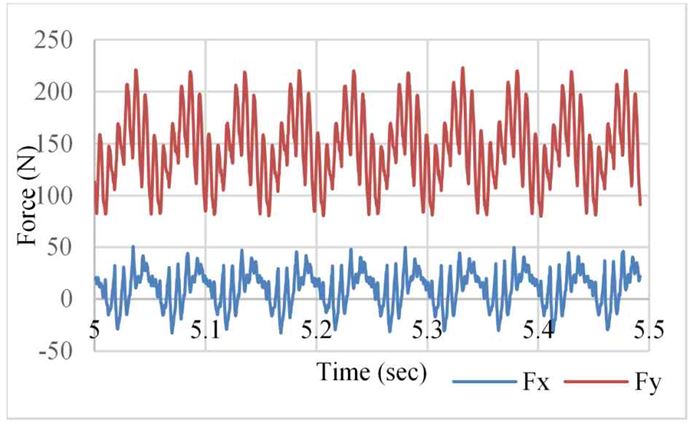
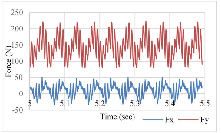
Figure 1 shows the in-plane milling forces in the X and Y directions during ten rotations. Figure 1a represents the fully dense material and Figure 1b represents the thin-walled supports (also called “block type” supports) with no trapped powder. The cutting force is higher in the fully dense material, and the forces steadily climb for six peaks, as each of the six teeth on the fluted end mill cut into the material (see Figure 1a). This process repeats every 0.05 seconds, consistent with the feed rate and speed of the cutting tool used in the experiment.
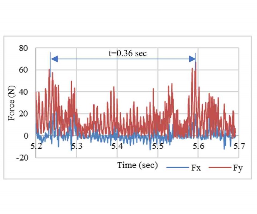
We see a much different signature for the thin-walled supports in Figure 1b. Every rotation of the tool encounters a different geometry (either thin-wall or hollow section or some combination of the two), and the resulting force varies as the mill travels across the support structure. The amplitude of the force is lower than when cutting the fully dense material, but the frequency is higher given the varying geometry. The pattern does repeat every 0.36 seconds based on the feed rate and speed relative to the spacing the support structure geometry.
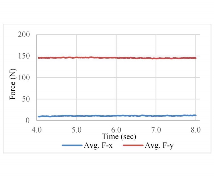
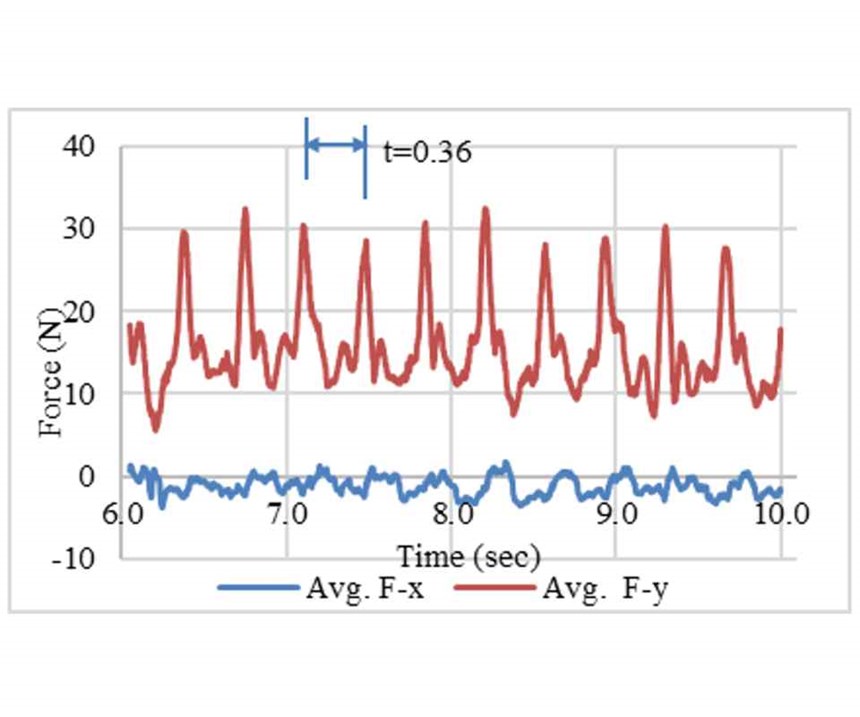
The difference between the support types is even more evident when we take a moving average of the cutting forces. As shown in Figure 2a, the average cutting force in the fully dense material remains flat in both x and y directions consistent with the homogeneity of the material that is being cut. This is markedly different to the data in Figure 2b, which shows the moving average of the cutting force when machining the thin-walled structures. The periodicity here corresponds to the distance between the thin-walled structures, and the peaks and valleys clearly show how the cutting forces increase when removing the thin-walled structures and decrease quickly thereafter.
Based on these averages, we can compute the corresponding cutting energy over time. In doing so, we find that the specific cutting energy for the thin-walled support structures is only 12 percent of that for the fully dense material. If we normalize this by the associated density of the material being cut, then that value jumps to 43 percent, indicating that the thin-walled support structures require less than half as much energy to be removed.
Based on this result, we would think that that would be good for tool, right? Not so. A tool wear study using a TiAlN-coated carbide end mill found flaking of the carbide coating after only three minutes when cutting the fully dense material using the recommended feed rate and speed for machining Inconel 718. When cutting the thin-walled supports, chipping at the cutting edges was observed after the first run, and the corner radii of the flutes cracked within one minute.
Was it just a bad tool? We thought it might be; so, we repeated the study multiple times with a new tool each time. Unfortunately, the same thing kept happening, and in one case, the corner radii of the flute fractured in 0.33 minutes when cutting the thin-walled support structures. So while the forces are less, the constant back-and-forth between the thin walls and hollow sections has significant and detrimental effects on tool life.
The results of both studies call into question the use of standard feeds and speeds when cutting away the thin-walled support structures that are commonly found on additively manufactured parts. So, for now, proceed cautiously when machining thin-walled support structures from metallic parts made via additive manufacturing. Alternatively, insist on fully dense support structures before machining, but even then, be prepared if your tool’s life is a lot shorter than you are used to seeing.
In closing, I want to thank my colleagues, Professor Ed De Meter and Dr. Guha Manogharan and the graduate students who helped conduct these experiments and analyze the results. If you are interested in reading more about the study, our full paper is now available in the Journal of Manufacturing Processes.
Related Content
10 Important Developments in Additive Manufacturing Seen at Formnext 2022 (Includes Video)
The leading trade show dedicated to the advance of industrial 3D printing returned to the scale and energy not seen since before the pandemic. More ceramics, fewer supports structures and finding opportunities in wavelengths — these are just some of the AM advances notable at the show this year.
Read More3D Printing with Plastic Pellets – What You Need to Know
A few 3D printers today are capable of working directly with resin pellets for feedstock. That brings extreme flexibility in material options, but also requires greater knowledge of how to best process any given resin. Here’s how FGF machine maker JuggerBot 3D addresses both the printing technology and the process know-how.
Read MorePostprocessing Steps and Costs for Metal 3D Printing
When your metal part is done 3D printing, you just pull it out of the machine and start using it, right? Not exactly.
Read MoreUnderstanding PEKK and PEEK for 3D Printing: The Cool Parts Show Bonus
Both materials offer properties desirable for medical implants, among other applications. In this bonus episode, hear more from Oxford Performance Materials and Curiteva about how these companies are applying PEKK and PEEK, respectively.
Read MoreRead Next
At General Atomics, Do Unmanned Aerial Systems Reveal the Future of Aircraft Manufacturing?
The maker of the Predator and SkyGuardian remote aircraft can implement additive manufacturing more rapidly and widely than the makers of other types of planes. The role of 3D printing in current and future UAS components hints at how far AM can go to save cost and time in aircraft production and design.
Read MoreHybrid Additive Manufacturing Machine Tools Continue to Make Gains (Includes Video)
The hybrid machine tool is an idea that continues to advance. Two important developments of recent years expand the possibilities for this platform.
Read More3D Printing Brings Sustainability, Accessibility to Glass Manufacturing
Australian startup Maple Glass Printing has developed a process for extruding glass into artwork, lab implements and architectural elements. Along the way, the company has also found more efficient ways of recycling this material.
Read More

