3D Printing with Plastic Pellets – What You Need to Know
Sponsored ContentA few 3D printers today are capable of working directly with resin pellets for feedstock. That brings extreme flexibility in material options, but also requires greater knowledge of how to best process any given resin. Here’s how FGF machine maker JuggerBot 3D addresses both the printing technology and the process know-how.
Share
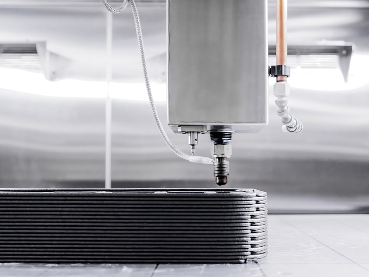
Close-up of JuggerBot 3D’s Tradesman Series™ P3-44 printer, equipped with Fused Granulate Fabrication technology.
Fused granulate fabrication (FGF) is an extrusion-based 3D printing technique where plastic granulates (AKA plastic pellets) are fed and extruded through a nozzle. FGF may be referred to as Fused Granulate Fabrication, Fused Particle Fabrication, or Pellet 3D Printing. Combining a plastics extrusion unit with a high-speed, precision motion system, FGF can achieve print speeds as much as 200X faster than fused filament fabrication (FFF). It is particularly well suited to printing larger parts and other cases where high deposition rates are desirable including near-net shape printing.
One of the best aspects of FGF is that it opens the door to work with a vastly broader selection of standard materials. But with that freedom also comes the need for knowledge of the processability of each material and the best process settings to achieve high-quality parts in the shortest, most efficient cycle times. JuggerBot 3D has been working on this very issue for years and has developed a 3D printing system with a range of adaptive and dynamic controls as well as a means to help users find the most predictable, repeatable and productive process for any given material without having to go through a time-consuming trial and error procedure. Here’s how they do it.
Fused Granulate Fabricating (FGF) Explained
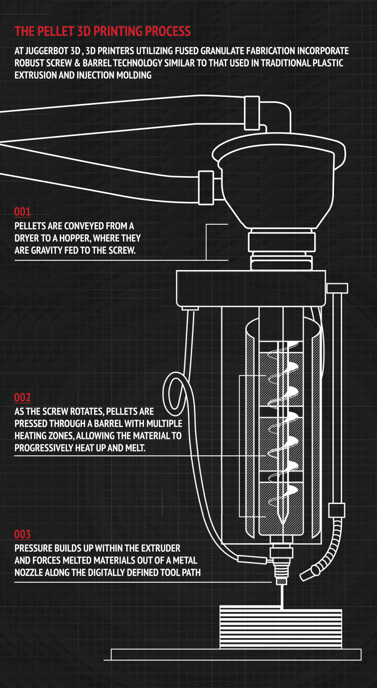
Click for full size image.
While they may look similar from the perspective of the print bed, FGF is considerably more complex than filament-based technologies. The process begins with a plastic resin extrusion unit that is very similar to what is used in the plastics industry. Pellets are conveyed from a dryer to a hopper where they are gravity fed to a screw that runs through a heated barrel. As the screw rotates, pellets are pressed through multiple heating zones which, combined with friction created by the screw, liquifies the material. As pressure builds up within the extruder it forces melted material out of a metal nozzle along a digitally defined tool path.
There are several key process variables that must be controlled to ensure a consistent and predictable FGF printing process. They include:
- Pellet size and geometry, which impacts the way material enters and flows through the system.
- Maintaining proper moisture content of material that is fed into the extrusion unit.
- Regulating the sequential heating zones in the extruder and print head to achieve safe and consistent flow of material.
- Adaptively and dynamically regulating screw speed to achieve the correct deposition rate.
- Applying an accurate motion control system to maintain precision at high gantry traverse rates.
- Precisely syncing extruder output with print head motion to assure consistent deposition bead size and shape.
JuggerBot 3D applies a range of smart technologies to manage all of these process variables in a way that requires little operator intervention once a process for a material is defined.
Why Dry?
While not all plastic resins absorb water a great many of them do, and moisture can collect on the outside of any pellet. Not having the proper moisture content going into an extruder can have a significant impact on the quality of the final product affecting both the appearance and the mechanical properties of the part. Also, variability of moisture content going in will deliver an inconsistent and unpredictable output. This factor affects both pellets and filament in 3D printing.
While controlling moisture is difficult with spooled material, drying technology for pellets has been around for more than 20 years and is capable of delivering extremely consistent material to the extruder. Arriving at proper drying parameters (heat, air flow, residence time) for a given material can be a process of trial and error. In the cases of JuggerBot 3D’s Tradesman Series™ FGF printers, however, the dryers contain an integral moisture sensor that helps manage drying process parameters to consistently deliver resin at the correct moisture setpoint, regardless of ambient plant floor conditions.
Managing the Bead
One of the most important aspects of achieving quality and consistency in a deposition process is how capable the system is at delivering and placing each bead of material in an extremely consistent way. This includes the bead shape, width, and layer height. There is a lot to control here because bead geometry may fluctuate due to material properties and stability, extruder temperature profile, extruder speed, gantry speeds for the deposition head, or environment. Inconsistent bead control can result in a variety of problems including voids in parts, over-build-up of material, dimensional inaccuracy and mechanical failures.

The Bead Characterization System plots a test path and analyses bead formation to calibrate the printing process for a given material.
The way JuggerBot 3D manages all these variables is with its Bead Characterization System (BCS) which is a method of collecting critical data points that characterize the bead deposited from the head of a 3D printing extruder relative to the remaining process parameters of the 3D printing system. In simplest terms, it is a sophisticated calibration system.
With this data, JuggerBot then applies Bead Area Mode (BAM) which is a method for generating tool paths for the 3D printing head. This way the entire tool path and process parameters can be generated based on the desired geometry of the bead.
The system manages and synchronizes a remarkable range of variables including:
- Extrusion speed – A specific screw speed must be established for each combination of material and extruder nozzle.
- Gantry velocity – The rate at which the motion system travels must be precisely synced with the extrusion deposition rate to generate a consistently sized bead.
- System latency – At the high traverse rates of FPF there can be a lag time between a CNC motion command and a servo motor executing that command. It’s like trying to drive a car around a corner too fast, and taking it too wide or too short, extending or cutting off the corner. JuggerBot’s controls take this factor into account either by manipulating the toolpath to insure a consistent head traverse rate or by dynamically slowing the screw speed to match an achievable traverse rate in specific circumstances.
Utilizing JuggerBot 3D’s Bead Characterization System
After initial parameters have been created through JuggerBot 3D’s Material Testing & Assessment procedure (see below), the Bead Characterization System is used to generate and print specific paths of varying parameters. Each path consists of multiple legs that represent a specific relationship between the material, the machine configuration, and the printing parameters. The results are then interpreted, either manually or through the use of an automated measuring device. The input of data then proliferates an entire set of parameters, utilizing a proprietary algorithm developed by JuggerBot 3D.
Once the BCS operation is complete, an operator can simply designate the specific bead width and layer height desired using Bead Area Mode within the slicer, and the remainder of the parameters are set based on the BCS data. This results in a significantly faster process that’s better fit for the dynamic nature of pellet-fed additive manufacturing.
Expert Help With Materials
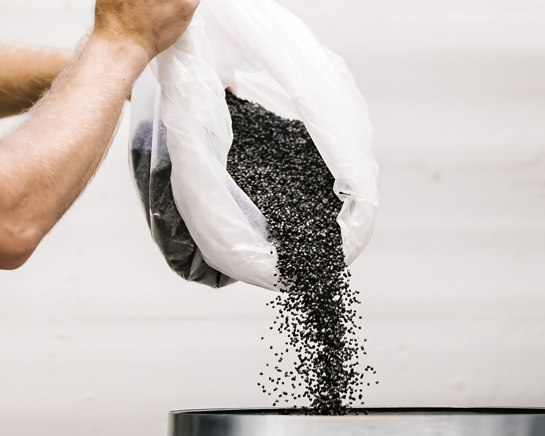
Pellets being poured into the dryer of the the Tradesman Series™ P3-44.
Having all these process controls enables the rapid generation of a high-quality and productive 3D printing process. BUT, this is only possible once the correct process parameters are defined for a specific material. For this JuggerBot 3D offers its Material Testing & Assessment (MT&A) process as a service. Using their Tradesman Series™ P3-44, and other required testing equipment, JuggerBot 3D will perform the procedure for any specified material. First, it verifies that JuggerBot’s 3D equipment is capable of processing the material and then it will be used as a benchmark for Material Qualification (MQ) as that material is processed for the production of functional parts. Major components of the MT&A procedure include:
Moisture Analysis – Once moisture parameters have been identified, each material to be tested will be dried to the manufacturer’s specification (temperature and duration) and tested for moisture content on JuggerBot 3D’s Computrac Max® 4000XL Moisture Analyzer.
Material Flow – JuggerBot 3D then tests material flow through their pellet extruder system to establish a temperature profile that includes barrel temperatures for the individual heat zones (3), nozzle temperature and a melt zone temperature. Residence time of thermoplastic material will be verified within identified temperature range and the flow of material will be visually inspected based on how shear affects extrusion properties. Using three specified extruder nozzle diameters (2.0mm, 4.0mm, 6.0mm), JuggerBot 3D performs a series of tests within a range of extrusion speeds to establish the material’s deposition/flow rates.
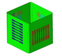
Standard test cube printed during the MT&A process. Test specimens can be extracted from the piece and used to evaluate material properties.
Bead Characterization – Material model parameters are obtained using JuggerBot 3D’s Bead Characterization System to increase the accuracy of layer dimensions and improve bead geometry control throughout the printing process. After calibration, Bead Area mode can be utilized within the tool path generator (slicer).
Printing of Test Specimens – Finally, samples are printed using recorded MT&A results to obtain specimens for mechanical testing using the specified nozzle diameters. Standard test specimens include a hollow cube or hexagon from which mechanical and thermal test specimens can be waterjet cut, a maximum overhang test for trapezoidal shapes and a maximum bridge test for pillars.
First Part Perfect
One of the longstanding issues with additive manufacturing is that it often takes a laborious and extended process of trial and error to arrive at a workable process to print any given part. The result is a huge investment of time preparing for each new job, which can be detrimental to business cases and makes 3D printing in production impractical.
At RAPID+TCT 2023, JuggerBot 3D unveiled their Material Card Database.
This digital product leverages findings from material testing capabilities to fuel smart printing process controls, while listing critical safety and performance-related properties for materials in pellet-fed additive manufacturing.
With this combination, manufacturers can get new jobs up and running much faster and with high confidence that new parts will meet dimensional and functional requirements right out of the box.
For more information please visit JuggerBot3d.com/material-card.