
A Framework for Qualifying Additively Manufactured Parts
A framework developed by The Barnes Global Advisors illustrates considerations and steps for qualifying additively manufactured parts, using an example familiar to those in AM: the 3D printed bottle opener.


Editor’s note: “Qualification” for parts made additively refers to and includes a variety of activities — which may or may not correlate to steps taken for other, more established manufacturing processes. This article lays out a framework for approaching qualification within AM developed by The Barnes Global Advisors, and applies the methodology to an object many in the space are familiar with: the 3D printed bottle opener. —Stephanie Hendrixson
Thomas Edison once said, "Opportunity is missed by most people because it is dressed in overalls and looks like work.” Additive manufacturing (AM) has the opportunity to create higher-performing designs that are more sustainable and cost less than legacy manufacturing, but we must first get to work demonstrating it is a reliable, repeatable process.


Today, there is much conversation about certification and qualification because this is the hallmark of success in the development and acceptance of new technology. The terms “certification” and “qualification” are often associated with regulated industries and demanding applications, such as aerospace and medical, yet they apply to all engineered solutions. The process is the same, but the testing intensity differs by application and industry. Even within aerospace, there is a range of options. The original AeroMet process (powder-fed directed energy deposition) used for the F-15 and C-17 parts 20 years ago used a combination of design allowable/welding approaches that entailed more than 3,000 coupon tests over four years. More recently, the approach for laser powder bed fusion (LPBF) parts for the A350 and A320 used a family approach that required significantly less testing, covering more parts.
In this article, we build on a prior article posted on The Barnes Global Advisors (TBGA) website describing qualification and certification activities and steps in detail. While the many regulatory bodies and certifying agencies have very detailed definitions unique to their field, in their simplest form the two terms are defined below:
What Is the Difference Between Certification and Qualification?
- Certification: A component that meets design intent is fit for service in a system.
- Qualification: A component meets design intent.
In future industry-specific articles, we will explore that while the outcome and process are the same, the testing and data requirements are influenced by the application and industry. For now, however, we'll define the various activities that make up the qualification framework and run through a simple, practical example. You might say we'll qualify how to pop open a fresh bottle to celebrate our way to illustrate how certification and qualification work (in a reliable, repeatable way).
An Additive Manufacturing Qualification Framework
To simplify, we’ve developed a TBGA AM Qualification Framework, which is common to all engineered products that encompass certification and qualification. It starts with requirements like the Systems Engineering V, using the 5 Pillars of Certification, and includes monitoring and tracking of production with a tie back to requirements. It also illustrates how the different aspects of the qualification are part of certification too. Note how the framework is dominated by requirements that must be met before moving to part/performance qualification and system certification.
Certification is granted by a regulatory agency or other independent authority; so, for this article, we are going to focus on qualification events as that is where most of us will be involved. The two are necessarily interrelated.
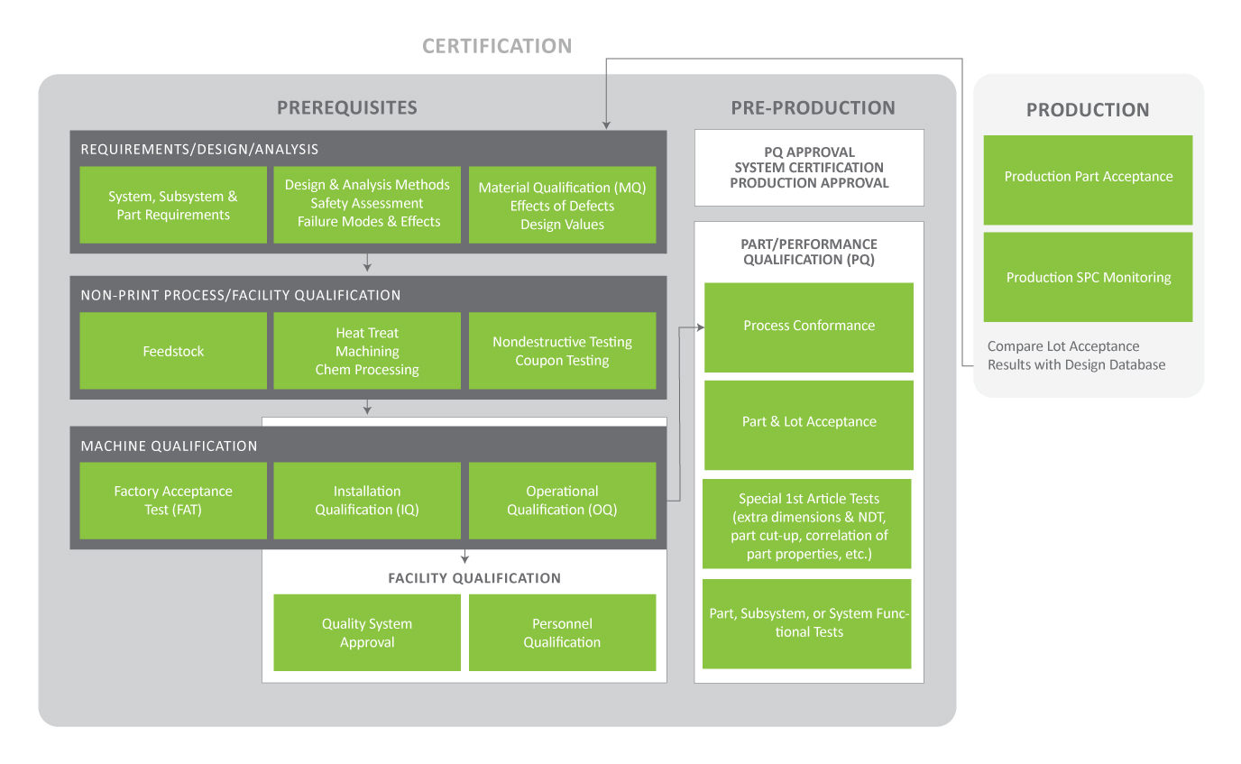
Certification granted by an independent authority takes into account multiple factors, many of which fall under qualification activities. (Click to enlarge.) Image Credit: The Barnes Global Advisors
Each category of activities within the certification and qualification workflow is defined below:
I. Prerequisites for Certification
Prerequisites for certification include establishing requirements for the application, as well as evaluating the feedstock source facility and equipment to be used for manufacturing.
a. Requirements/Design/Analysis
Requirements are essential prerequisites to start the process. The requirements of the part are not influenced by how the part is manufactured. The design and analysis may differ because AM affords the ability to make geometries that have not been previously used (lattices, topology optimized, etc.). New analysis methods for stresses, buckling, margins of safety, failure modes, etc., may need to be developed and analyzed.
Similarly, Material Qualification (MQ), a subset of Part/Performance Qualification (PQ), can refer to a range of activities such as determining impacts of process or geometry on material properties, characterization of non-standard properties, and determining variation between printers. There is often an overlap between printing and testing for MQ and in the generation of design values.
b. Non-Print Process/Facility Qualification
This activity is identical to the qualification of legacy methods like wrought products, where key manufacturing and inspection/acceptance processes require qualification. However, in the case of feedstock, the main question for the qualifying organization is determining if the feedstock facility (or even manufacturing line) will be qualified based on its own merits (composition, powder size distribution or wire diameter, method of manufacture), or if qualification also requires evaluations of the feedstock in printed material.
c. Machine Qualification
In the manufacturing of wrought products, a facility will often only have one set of equipment (breakdown press, rolling mill, stretcher) to make a given product, making facility and equipment qualifications the same. AM appears to be unique because a facility can have many printers and lacks tooling. In the case of die forgings, qualification is driven more by the tooling and schedule, which are covered in PQ. In the case of critical parts, qualification is required for every press and die set. Relative to AM, as with any process, Aerospace Industries Association (AIA) best practices recommend a three-part machine qualification: FAT, IQ and OQ.
- Factory Acceptance Testing (FAT): FAT verifies the printer operates properly and is performed by the printer manufacturer before delivery. FAT ensures the customer that the printer has a known default condition.
- Installation Qualification (IQ): IQ verifies the printer is fit to make hardware and is performed at the user’s site. This is sometimes called Site Acceptance Testing (SAT). SAT and FAT will be very similar, but SAT may involve a different alloy, specific geometries, motions and energy levels than were covered in FAT.
- Operational Qualification (OQ): OQ verifies the printer material meets a given specification and is performed at the user’s facility after IQ is complete. This requires making one or more builds of test coupons, performing required thermal treatments, and NDT. The coupons are subjected to compositional, microstructural and mechanical tests, and results are compared with the requirements and material specification. OQ is required for each specification requirement.
II. Pre-Production Qualification
Once prerequisites have been met, manufacturers must qualify the facility and part before production can begin.
a. Facility Qualification
Facility qualification requires an approved quality system such as ISO-9001 or AS-9100, qualified personnel, and qualified equipment (i.e., at least one printer would have successfully passed OQ). This is the same as with legacy forms of manufacturing.
b. Part/Performance Qualification (PQ)
Once all the prerequisites are met, PQ entails producing one or more qualification parts and performing:
- Process Conformance: Manufacturing of the qualification part(s) must conform to the drawing and process requirements (feedstock, print, heat treat cycle, etc.).
- Part and Lot Acceptance: All qualification part(s) must pass part (dimensional, nondestructive testing [NDT]) and lot (composition, witness tensile, microstructure) acceptance tests.
- 1st Article Tests: For the 1st article, unique tests may be required that won’t be included in production. Examples include supplementing NDT with computed tomography (CT), more dimensional measurements, destructive testing of the part, and coupons, all of which need to meet the material specification requirements.
- Part, Subsystem or System Functional Tests: In this activity, the testing can range from a simple static proof test, to elaborate multi-axial or fatigue tests up to a subsystem or system test. A subsystem test could be installing a landing gear beam into a landing gear assembly, while system testing involves the final system, like a flight test for an aircraft.
c. PQ Approval / System Certification / Production Approval
Upon completion of qualification testing, the qualification test report will be approved by the Cognizant Engineering Organization (CEO), followed by the certification of the system with the AM hardware and production approval.
III. Production
Once in production, continuous monitoring ensures the parts are equivalent to those used for qualification.
Examples could include Statistical Process Control (SPC) of key process variables, lot acceptance values, and part acceptance rate, to name a few. Additionally, the results of lot acceptance values should be statistically analyzed and compared to the material database used to develop design values to ensure process drift or scatter has not occurred.
Simple Example – Bottle Opener
To illustrate how the framework is applied, we will use an example familiar to everyone in the AM world, the ubiquitous bottle opener.
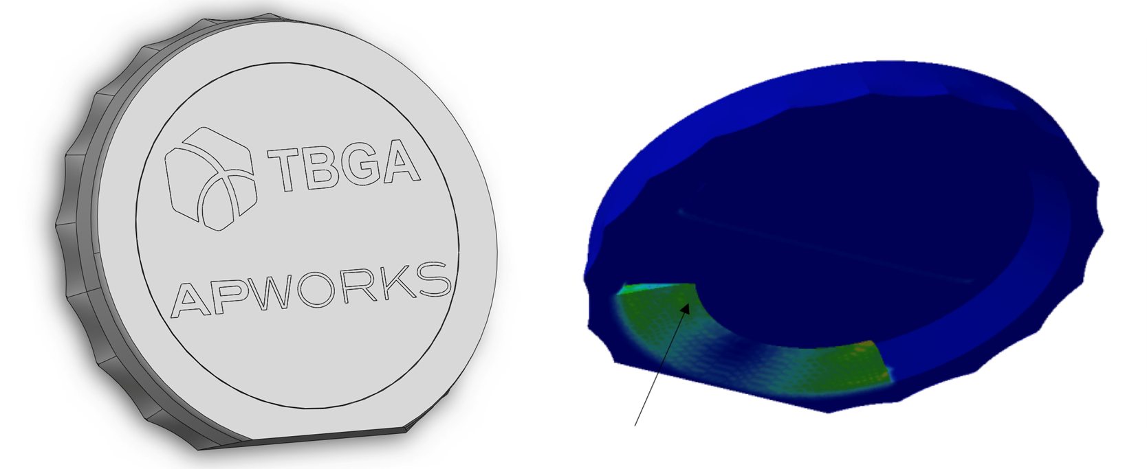
This is one of three bottle opener designs assessed. The desire to incorporate logos in a bottle opener that could fit in the palm of the hand favored LPBF as the production method. Photo Credit: The Barnes Global Advisors
I. Prerequisites
a. Requirements/Design/Analysis
The first step was to develop a set of requirements sought by the team. The full list is noted in this earlier publication. Amongst the full list, we included both functional and commercial needs for the opener.
The bottle opener in this assessment needed to fit in the hand and be eye-catching, as well as incorporate a logo. This requirement favored the use of LPBF as the manufacturing process.
In terms of performance, failure of the device with less than 1,000 openings was considered unacceptable. We were able to estimate the loading for the cap on a bottle and perform simple calculations based on the expected failure mode. This requirement helped inform the material selection with appropriate thermal treatment.
b. Non-Print Process/Facility Qualification
Given the requirements, this step was minimal. The powder feedstock needed to meet AMS7073, and the stress relief furnace used had to be capable of achieving and holding the necessary temperature based on prior runs for other cycles. Machining, coupon testing and nondestructive testing were not required for the bottle opener.
c. Machine Qualification
It was determined that proof that a FAT and IQ had been performed and calibration and maintenance records could be provided was sufficient.
II. Pre-Production
a. Facility Qualification
The team assessed the chosen facility’s qualification approval for aerospace coupled with the machine qualification as meeting the bottle opener requirements.
b. Part/Performance Qualification (PQ)
Like the prerequisites, PQ was simplified for the bottle opener:
- Process Conformance: Feedstock conformed to AMS7037. The printing was successful, with no disqualifying faults. Stress relief was within specification.
- Part and Lot Acceptance: All parts met dimensional and surface finish requirements. No composition, tensile, or metallographic tests were required.
- 1st Article Tests: Not applicable.
- Part, Subsystem, or System Functional Tests: Each opener in the build was subjected to proof testing at 25°C. All tests were successful (and delicious).
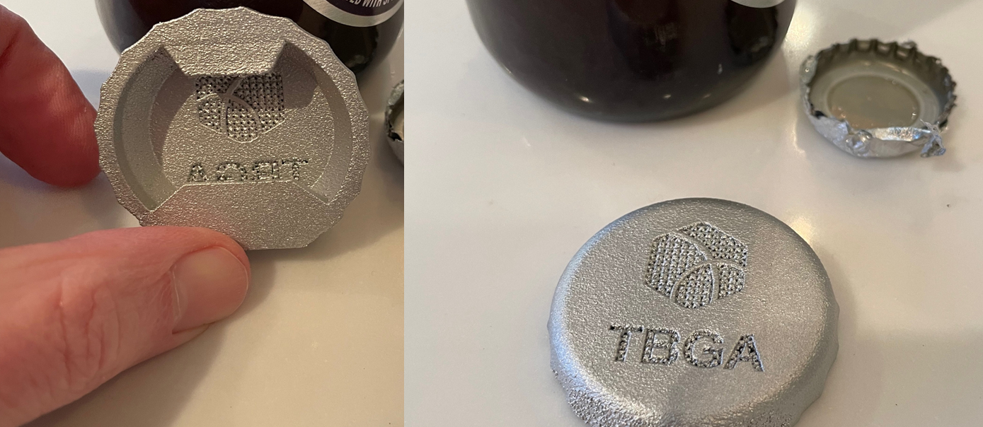
The proof test shows an open bottle with no obvious deformation to the opener. Photo Credit: The Barnes Global Advisors
c. PQ Approval / System Certification / Production Approval
Completion of the qualification test, combined with the prior stress analysis and failure modes analysis, demonstrated all the certification criteria were met, resulting in the certification of the bottle opener. Production approval is in the works.
III. Production
Production monitoring will consist of tracking feedstock composition, printer output and heat treatment cycles for conformity.
Combined Efforts for Qualification
Qualification is done every day in every industry and every application. Hopefully, we have clarified what we mean by certification and qualification. Within qualification, we have discussed several paths. The combination of these efforts results in what we call the TBGA AM Qualification Framework. While it seems difficult, remember it is a team effort. Most people won’t be involved directly in a qualification event, but most engineers will contribute to its reality. Any part once qualified, (as with the bottle opener), affords that the product is safe. Modifications can be made, which would only require supplemental testing, not starting anew. All this hard work creates opportunity.
More complex examples of the framework will be provided in the coming months. In these, we will eventually show how standards inform specifications, specifications inform design and procurement, and ultimately, we get to an “allowable” which supports safe design. The first of these will include Paul Gradl, NASA on Space, Tom Cobbs, BAE Systems on Defense, and Anthony Mott, Wabtec on Rail.
About the Authors
John E. Barnes
John Barnes is president and founder of The Barnes Global Advisors, as well as CEO and cofounder of Metal Powder Works. His 30+ year career in product development and aerospace includes positions at Honeywell, Lockheed Martin, CSIRO and Arconic. He can be reached at john@barnesglobaladvisors.com.
Kevin T. Slattery, D.Sc
Dr. Slattery is a principal ADDvisor for The Barnes Global Advisors focused on metals manufacturing, qualification and certification. He previously served as chief scientist for AM at Boeing Research & Technology (BR&T) and holds 34 U.S. patents. He can be reached at kevin@barnesglobaladvisors.com.


Related Content

3D Printing with Plastic Pellets – What You Need to Know
A few 3D printers today are capable of working directly with resin pellets for feedstock. That brings extreme flexibility in material options, but also requires greater knowledge of how to best process any given resin. Here’s how FGF machine maker JuggerBot 3D addresses both the printing technology and the process know-how.
Read More
How to Build 10,000+ Shot Molds in Hours
Rapid tooling isn’t so rapid when it takes days to 3D print a metal mold, and then you still must machine it to reach the necessary tolerances. With Nexa3D’s polymer process you can print a mold in hours that is prototype or production ready and can last for more than 10,000 shots.
Read More
Understanding HP's Metal Jet: Beyond Part Geometry, Now It's About Modularity, Automation and Scale
Since introducing its metal binder jetting platform at IMTS in 2018, HP has made significant strides to commercialize the technology as a serial production solution. We got an early preview of the just-announced Metal Jet S100.
Read More
AM 101: What Is Binder Jetting? (Includes Video)
Binder jetting requires no support structures, is accurate and repeatable, and is said to eliminate dimensional distortion problems common in some high-heat 3D technologies. Here is a look at how binder jetting works and its benefits for additive manufacturing.
Read MoreRead Next

3D Printed Replacement Clamp for an F-16 Aircraft: The Cool Parts Show #54
3D printing is a valuable addition to sustainment programs, but only if printed parts can be qualified as fast and flexibly as they can be made. In this episode of The Cool Parts Show, we look at the clamp that won the Air Force’s Approval Sprint Challenge designed to address this need.
Read More
Qualification Today, Better Aircraft Tomorrow — Eaton’s Additive Manufacturing Strategy
The case for additive has been made, Eaton says. Now, the company is taking on qualification costs so it can convert aircraft parts made through casting to AM. The investment today will speed qualification of the 3D printed parts of the future, allowing design engineers to fully explore additive’s freedoms.
Read MoreThe New Misperceptions Of AM: AM Radio #35
Tim Simpson and Peter Zelinski discuss a way additive manufacturing has advanced: The misperceptions have shifted. Knowledge of AM among manufacturers is more sophisticated now. The concerns that inform the perceptions of newcomers have therefore changed.
Read More