
Additive’s Idiosyncrasies
Additive manufacturing is not as easy as just hitting “print.” Like any manufacturing process, it demands attention to considerations that are characteristic of this process alone.
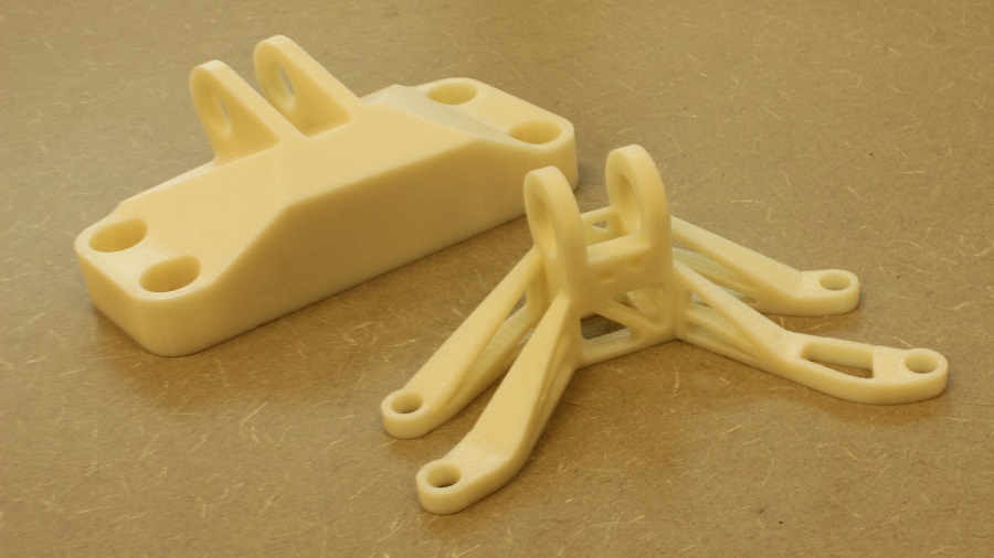
Fig. 1 — In the background is a plastic model of an existing metal bracket for an aircraft. The optimized design in the foreground, which would be produced additively, could meet the design requirements for the bracket with 88 percent less part weight. Software tools unfamiliar to many designers are necessary to pursue this kind of optimization.
Important process considerations in additive manufacturing include (1) the support of the part during the additive build and (2) the part’s orientation. These choices are interrelated, as seen in this “cage” part with vertical fins that was additively produced at the CIMP-3D facility.
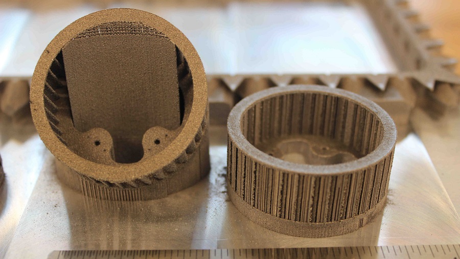
When the cage part is built in a level orientation, supports are needed between the fins to hold the form as it grows. These supports later have to be removed. But when the part is grown at a 45-degree angle, those supports between fins are not needed.
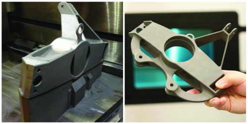
Fig. 2 — Support is a significant consideration affecting the cycle time and material use of a given part. Support structures for this additively manufactured component accounted for half of its build time.
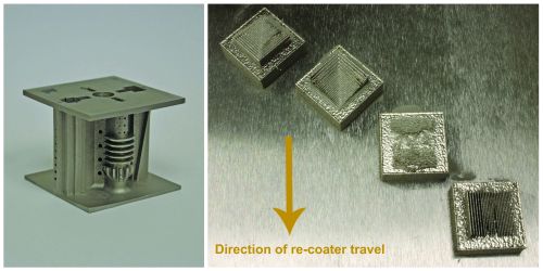
Fig. 3 — Here are two illustrations of the effect of part orientation. The part below was produced by three different additive manufacturing suppliers. The components they delivered were all different, because each supplier chose to orient the part in a different way. At right, delicate features are produced with differing levels of success depending on their orientation with respect to the machine’s moving blade.
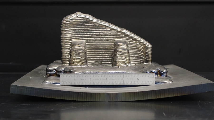
Fig. 4 — Residual stress was sufficient to warp a 3/4-inch steel plate. One solution is to build mirror-image parts on opposite sides of the plate, thereby balancing the stresses.


There is this photo I’ve seen from an organization promoting additive manufacturing technology. Which organization doesn’t matter, because various companies marketing the technology have created images like the one I am thinking of. What this particular image shows is an at-ease young person, possibly a young engineer, casually pulling an intricate finished part out of a 3D printer.
The photo is not necessarily false. However, it allows a certain false impression to stand. Namely, the impression that additive manufacturing is easy, that it is different from other manufacturing processes in being casually simple to use to obtain the part as intended.


In fact, just the term “3D printing” is unfortunate in this respect. That term implies that direct digital part-making is somehow as seamless and as straightforward as using a document printer. To be blunt, it is not.
Yet saying this does not detract from additive manufacturing’s promise. Because of the design freedom it offers—plus its efficiency at low volumes, plus the opportunity it offers to consolidate assemblies, save material and reduce weight—additive manufacturing seems all but certain to take its place as an established, accepted option for part production. But like all other production options, additive manufacturing has part and process considerations all its own. It has engineering considerations all its own. It even offers plenty of room for failure, and the shops adopting additive manufacturing for metal parts in particular face a learning curve that is likely to be extensive.
One organization that helps companies with ascending that learning curve is the Center for Innovative Materials Processing through Direct Digital Deposition, or CIMP-3D, at Pennsylvania State University. The faculty and researchers in this facility work with companies interested in additive manufacturing to explore processes such as direct metal laser sintering (DMLS), electron beam additive manufacturing and laser metal deposition. For all of these technologies, the value CIMP-3D offers is that it can help companies move more quickly through the trial-and-error period with additive manufacturing by guiding them in investigating the variables to obtain an additive process that is ready for their own particular, proprietary ongoing production.
What are these variables? I recently had a chance to speak about this with Timothy W. Simpson, Ph.D., professor of mechanical and industrial engineering and a co-director of the center, as well as CIMP-3D R&D engineer Corey Dickman. Some of the variables in an additive process involve the adjustable parameters of a particular additive manufacturing machine. The user of a DMLS machine, for example, might alter the laser power and beam diameter for different jobs and different alloys. But other considerations are more universal to the nature of additive manufacturing. Just as CNC machining has inputs affecting success (such as cutter selection, feed rate and the rigidity of the workholding), additive manufacturing has comparable inputs that affect its success—inputs that the user of additive manufacturing learns to apply over time. Describing these inputs is helpful for developing a more realistic picture of what it’s like to apply additive manufacturing in production. Here, then, are some of the factors that the user of additive manufacturing learns to consider:
1. Topology
To say that additive manufacturing permits complex parts does not go far enough, says Dickman. It does indeed permit this—growing a part in digital layers means that intricate structures for reduced weight are easy to create. However, the fuller truth is that additive manufacturing actually prefers this complexity. Tailoring the form of a part to match only the load that part has to carry and the service it has to perform results in an additive build that uses less material, requires fewer supports while the part is growing and is less prone to the accumulation of residual stresses.
Figure 1 shows an example. Penn State graduate student Jessica Menold submitted this entry in a GE-sponsored contest to redesign an aircraft bracket. Her design, if produced in metal, would be 88 percent lighter than the bracket that had previously been in use, while still meeting the design requirements for this part.
Yet how does the engineer who is seeking this kind of design optimization—that is, this kind of improvement through subtraction—actually know what material to subtract and what form ultimately matches the load paths in the part? Most design engineers have not had to face these questions, because they work with constraints so common to manufacturing that we don’t even think of them as constraints. That is, designers are usually required to begin with a solid block or semi-net-shape form, machining away material to obtain external features. Elaborate forms are beyond consideration because machining can’t produce them. Take this limitation away, and the resulting freedom is actually too vast for an unassisted engineer to know what form to select.
That is why additive demands a different approach to design, Dickman says. Software tools operating at a higher level than traditional CAD are employed to begin with boundary conditions defining the part’s function and available space. These tools then calculate an efficient geometric form for those conditions through iterative mathematical analysis.
Most machine shops have never heard of these software tools, but they do exist, and CIMP-3D has grown accustomed to them. One choice at the high end, Dickman says, is Altair Optistruct. This software’s geometric calculations are sophisticated enough that the software might need to be left running all night to perform a topology optimization for a particular form. Less capable but easier-to-use optimization tools include SolidThinking Inspire, he says, as well as freeware options such as TopOpt.
2. Supports
One of the problems with the false picture of additive manufacturing literally “printing” a ready-to-use part is that this picture overlooks the amount of physical support the part is liable to require while being built. In metal additive manufacturing, support structures help transfer heat away from the part as new additive layers are added and also help hold the part’s shape as it forms. A typical step in the design of a part produced additively is designing its support structures.
Figure 2 gives an example of how extensive these support structures might be. The component relates to a project by a Penn State undergraduate student, Vincent Maranan, who applied additive manufacturing to produce a wheel’s upright (connecting the hub and brake calipers to the suspension arms) for a competition involving student-designed race cars. On this part, the supports that were needed to preserve the bow-like features, the triangular peak and the large central bore together accounted for 50 percent of the build time for this part.
How are supports such as these removed when the build is complete? Additive manufacturing of metal parts still lacks an automated way to perform this step. Thus (perhaps strangely), one of the most advanced metalworking technologies is often followed by one of the most primitive. The supports on end-use production parts that are made through additive manufacturing are often removed with hand tools including a hammer and chisel.
3. Orientation
Did the part in the previous example have to be built so that it stuck up into the air like a shark fin? Maybe not. It could have been laid down on its side. Less support material would have been needed in this arrangement, and with less vertical height to cover, the build time would have been much less. But in this orientation, certain features of the parts might not have formed as accurately. Growing the part at something near a 45-degree angle might have offered an effective compromise. In additive manufacturing, searching for the right orientation of the part is an important aspect of finding the most efficient and effective process.
Simpson says this is part of the reason why the CAD model by itself no longer conveys enough information to define the part. CIMP-3D saw a demonstration of this in a recent experiment in which it sent the same CAD model to three different providers of additive manufacturing services. Penn State graduate student Andrew Coward, who is involved in gas turbine research, designed a complex test part with features relevant to turbine components. All three additive suppliers were asked to produce the test part on their DMLS machines. Unknown to one another, all three independently chose to orient the part in different ways, and all three produced different results. Coward actually got back four parts, because one of the three suppliers tried it two different ways. Each of the resulting four parts was true to the CAD model in some details and violated it in others, and each part’s set of true features and faulty ones was different from all of the others.
The test was rigged, Simpson says. The part was designed with internal and external features in so many opposing directions that no single DMLS build could generate all of them perfectly. What the test shows, he says, is the kind of thinking that designers have to put into an additive-manufactured part. Even dimensional requirements are not necessarily helpful. Design engineers instead must prioritize which part features are more critical and which features can be left free to slightly depart from the model. For example, every model hole through a part is likely to be defined with a circular cross section, because designers are accustomed to holes being drilled. Simpson points to this as an example of a basic design assumption that now needs to be examined. That is: Which holes truly need to be circular?
He adds that the orientation of the part relates to more than just the direction of layers of material. On the DMLS machine, there is a recoater blade that might affect a delicate feature of the part or might leave it unharmed, depending on the orientation of this feature with respect to the blade. Figure 3 shows this.
4. Residual Stress
Alternatively, an additive-manufactured part might depart from the CAD model not because of any effect of its orientation, but instead because of residual stresses that accumulate as the part solidifies during the build.
The metallurgical formation of an additive part is complex, Dickman says. It is not precisely true that a given layer is added to the part as a liquid and becomes a solid thereafter. Instead, a given layer is affected by the heat of the layer added directly above it, somewhat less by the heat of the layer above that one, and on and on. Any layer of material thus continues to heat and cool, settling into its final integration with the rest of the part only gradually. The heating and cooling affects the material microstructure and creates residual stresses that build up in the part. Modeling this behavior so as to predict potential distortion from these stresses is one of the more important areas of CIMP-3D’s additive manufacturing research.
The effect might be insignificant for a small part built within the typical additive manufacturing machine envelope. Yet the effect becomes pronounced as build sizes grow. The facility’s electron beam additive manufacturing machine from Sciaky can build parts as long as 85 cm. Figure 4 shows an extreme example of the residual stress the facility has found in such large components. A 3/4-inch steel plate became bent 3/4 inch at each end because of the forces built into this part as it was formed. The second photo in this figure illustrates a solution Sciaky has applied to this problem: building mirror images of the same part on opposite sides of the plate in order to balance the forces.
5. Powder
On a powder bed machine, says Dickman, the metal powder is expensive enough that a user needs a strategy for reclaiming and reusing powder left over after the build. The problem with this is that the powder at the end of the cycle is slightly different from the powder that began it. Smaller particles are inclined to melt more readily and tend to agglomerate onto the larger particles, so the leftover powder is biased toward larger particle sizes. Depending on the material purity requirements of the application, it might be possible to mix this leftover powder with virgin powder. But even at that, how many cycles is the powder good for before it has changed too much to assure a quality part? In any additive manufacturing process aimed at ongoing production, he says, the answer to this question has to be part of the process specifications. For CIMP-3D and other additive manufacturing organizations, the implications and best practices of powder recycling is another active area of study.
He notes as well that plenty of powder is lost in the machine’s filter during the build—maybe as much as 40 percent of the weight of the part. That loss is in addition to the material that is lost to the support structures that are cut away and discarded. The notion that additive manufacturing is a process free of waste or scrap simply is not true, he says.
6. Material
One final process consideration is perhaps the most fundamental: the metal from which the part is made. The choice of metal for a machined part might not be the right choice if that same part is redesigned to be produced additively. The design freedom of additive extends to the choice of material, because some materials that are difficult to machine are actually easy to apply in additive.
The reverse is also true. Some aluminum alloys, for example, while easy to work with in machining, are more difficult to process using a laser-based additive process. Meanwhile, titanium alloys, which might be seen as challenging to machine, are the most proven and best-understood metals when it comes to additive processing. In fact, the ideal material for a topology-optimized form (point number 1) is likely to be titanium, because of its strength-to-weight properties. And if the optimization removes enough material from the design, then the new titanium part is likely to be lighter than the previously solid part, even if the previous part had been machined from aluminum.
Though we seldom think of this, says Simpson, part materials are usually selected with an eye toward machining. Hard-to-machine materials have a strike against them in winning acceptance. Now, he says, it’s time to change that mindset, because that criterion biases us against certain metals that deserve to be more popular than they are.
Inconel, for example, has favorable properties appropriate to a range of applications. It should be used more widely than it is. It’s just that it’s difficult to machine. But in a near-net-shape additive process in which the amount of stock to be removed through machining is much less, Inconel might be free to play a larger role.


Related Content

3D Printed NASA Thrust Chamber Assembly Combines Two Metal Processes: The Cool Parts Show #71
Laser powder bed fusion and directed energy deposition combine for an integrated multimetal rocket propulsion system that will save cost and time for NASA. The Cool Parts Show visits NASA’s Marshall Space Flight Center.
Read More
Video: A Mechanical Method for Metal Powder Production
Metal Powder Works has developed a method for producing powders from solid barstock, no melting required. This video covers how the process works and benefits of mechanical production of powders.
Read More
3D Printed Replacement Lever Arm Keeps Critical Waterway Open: The Cool Parts Show #83
Lincoln Electric and the Army Corps of Engineers collaborated to deliver a 3D printed alternative to a failing legacy casting found in the Soo Locks, the lock system connecting Lake Huron and Lake Superior.
Read More
Video: 5" Diameter Navy Artillery Rounds Made Through Robot Directed Energy Deposition (DED) Instead of Forging
Big Metal Additive conceives additive manufacturing production factory making hundreds of Navy projectile housings per day.
Read MoreRead Next

Additive Manufacturing Versus Cavitation
The design freedom possible with laser powder bed fusion (LPBF) metal 3D printing is making it faster and easier to produce complex anticavitation devices for valves.
Read More
Three Drivers of AM Materials Development and Adoption
Lack of material options is becoming an outdated reason not to use additive manufacturing. But what factors are driving the creation — and use — of new materials for AM?
Read More
In the News: Distributed Manufacturing 8,000 Miles Apart
The U.S. Navy’s Fleet experimentation exercise demonstrated field-deployable 3D printing and on-demand production through Stratasys Direct. Why it matters: Distributed manufacturing adds resilience to supply chains and increases military readiness.
Read More