
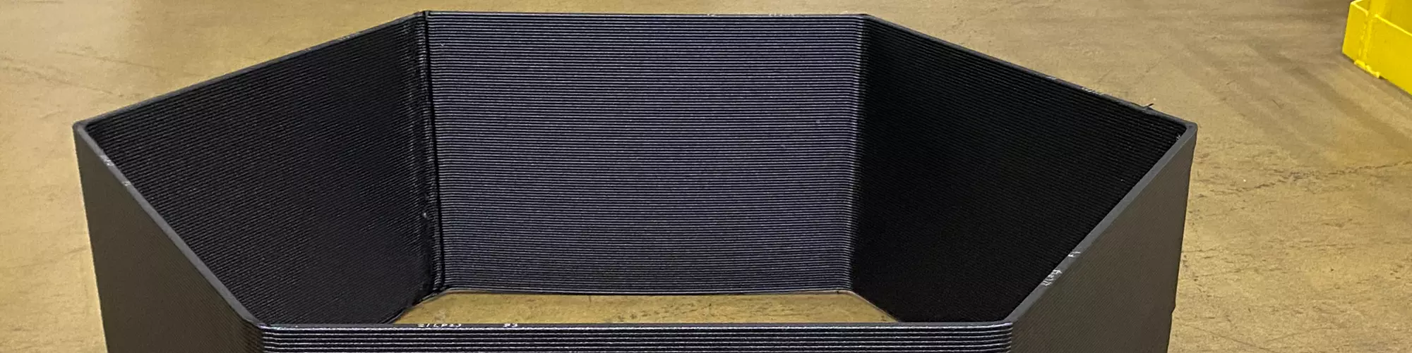


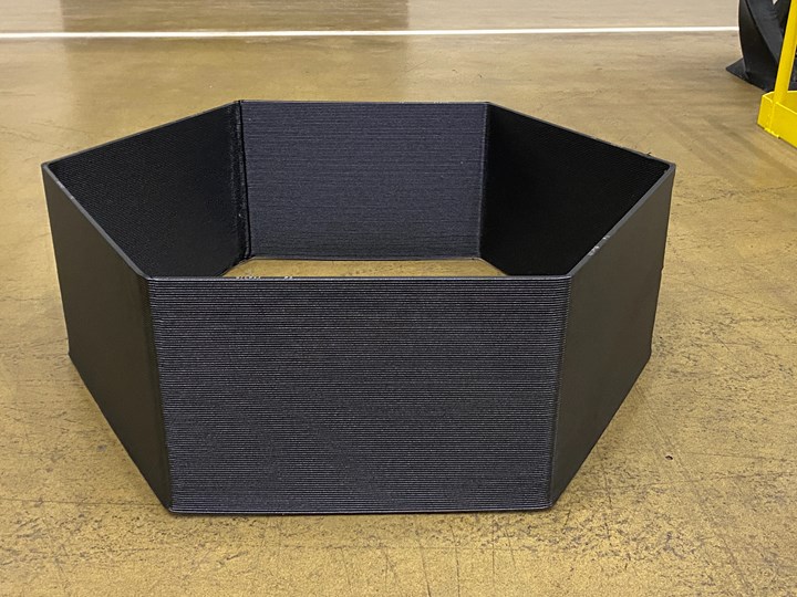
Figure 1: A completed hexagonal test print using LFAM regrind. Photo Credit: SABIC
Additive manufacturing offers freedom of design and the ability to make tools and end-use parts in a more efficient and sustainable way. By printing parts that are close to final shape, this process reduces the amount of subtractive waste that is generated for enhanced efficiency and sustainability. It also uses less energy to produce the part than traditional molding and offers opportunities for recycling excess material or parts to promote circularity.
Large-format additive manufacturing (LFAM), a subset of additive manufacturing, is growing in popularity. As LFAM usage expands, there are increasing concerns about what to do with large parts and scrap materials when a project is finished, other than landfilling (Figure 2).


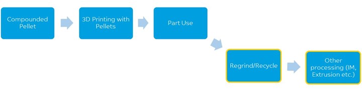
Figure 2: Potential life cycle of material used in LFAM. Photo Credit: SABIC
Initially, LFAM was used primarily to print one-off parts for prototypes or demonstrators, so there was little material to be reclaimed and recycled. As LFAM applications diversify to include end-use parts as well as tooling, jigs and fixtures, there are more shavings and end-of-life parts that need to be disposed of — ideally in sustainable ways. Manufacturers that use LFAM want to be responsible, but currently there is no established process for re-using LFAM scrap and parts. To advance this issue, SABIC and Local Motors completed a study to verify the viability of using LFAM regrind in manufacturing processes. This study, which looked at the printability and mechanical properties of reground LFAM parts and shavings, demonstrates that extending the useful life of this material is indeed possible.
Reusing LFAM Parts and Shavings
SABIC and Local Motors studied the option of regrinding LFAM printed parts and machine shavings and the effect that would have on reprocessing the material in a LFAM printer. Reclaiming material this way is considered mechanical breakdown, in that the grinding process shortens the reinforcing fibers in the final pellets, which can reduce overall mechanical performance. In addition, when a polymer is put through multiple heat cycles (grinding, re-pelletization, re-compounding, etc.), this cumulative heat history breaks down the polymer chains and can degrade performance. However, mechanical recycling has long been used in plastic injection molding with success; reground sprues, parts and runners can be incorporated back into the process with acceptable results when good housekeeping practices are followed.
Based on the companies’ experience with LFAM processes, SABIC and Local Motors were aware that LFAM printers can be more sensitive to inconsistencies in material feed than injection molding and standard extrusion processes, due to the need to optimize print layer uniformity. Given the small barrel sizes and short residence times typical of LFAM machines, thoroughly mixing reground material in the barrel would be more difficult than with injection molding and standard extrusion processes, potentially leading to greater inconsistencies in the material. With that in mind, the two companies decided to have the regrind material pelletized before conducting the blending and printing study.
The challenges associated with grinding LFAM parts and shavings stem from the large part sizes involved and the possible contamination with other elements. There is a limit to the size of a part that can fit into a grinder. Also, foreign materials could be present and potentially contaminate the regrind. These substances could include metal from machining and milling processes; build sheet residue attached to the part; and in-use contaminates (e.g., cement dust, adhesives, Bondo) that might adhere to the part or be mixed in the shavings. Separating out contaminates and cutting down parts into acceptable sizes would be necessary to make the material more suitable for conventional grinding processes.
This study focused on SABIC’s LNP Thermocomp AM compound, a carbon fiber-reinforced grade for large-format additive manufacturing. (The material has been used for autoclave tooling, among other applications.) Local Motors cut down the LFAM parts into 12-inch-square blocks, making them easier to grind. An outside company was contracted to grind up the blocks and re-pelletize, package and ship the material to SABIC’s Polymer Processing Development Center in Pittsfield, Massachusetts, for printability and mechanical performance studies.
Evaluation of LFAM Regrind for Reuse
There were two parts to the evaluation of the reground material: 1) printability and 2) mechanical performance. To begin the evaluation, the reprocessed Thermocomp AM compound and virgin materials were manually blended to produce 100-pound samples containing 0, 15, 25, 50, 75 and 100% reprocessed content. Both types of material were in pellet form for ease of blending and feeding into the LFAM machine.
Printability Evaluation
To assess the printability of the material samples, a throughput test was performed, and a single-wall hexagon was printed for each sample (the hexagon is SABIC’s typical test part geometry for processing and material characterization) using SABIC’s Big Area Additive Manufacturing (BAAM) machine from Cincinnati Inc. Each printed part was examined and compared to a control part printed from 100% virgin material to evaluate surface appearance, consistency and print defects.
Throughput Test
A throughput (purge) test was conducted with each of the materials. After setting the temperature melt profile for the resin and purging for 10 minutes to ensure the equipment had reached thermal stability, the material was purged in various settings and locations to cover all rpm (revolutions per minute) conditions (100, 200, 300 and 400 rpm). Purge piles were allowed to cool and then weighed. During each purge step, the material was observed for melt fracture or other extrusion anomalies as it exited the nozzle.
The throughput test showed that material flow was relatively consistent among the six samples, with one exception related to the 400 rpm purge test rate. Due to the viscosity shift of the material, which occurs as increasing amounts of regrind are added, the sample with 100% regrind was able to complete the 400-rpm purge test. With lesser amounts of regrind (i.e., 0 and 15%) the machine torqued out, preventing the testers from completing the 400-rpm purge test. Because the 25, 50 and 75% regrind loaded samples appeared to print in a similar way as the 0 and 15% samples, the 400-rpm condition was omitted for them. The increased flow seen with the 100% regrind sample prompted the attempt of the 400-rpm condition, resulting in a successful outcome.
Printing of Single-Wall Hexagon
Once a temperature profile was selected, as determined by the above purge pile procedure, a single-wall hexagon was printed for each sample. At the start of printing the machine was further dialed in by adjusting print speed to achieve a bead size of 0.4 inches wide by 0.15 inches high. The hexagon’s sides measured 22 inches wide by 15 inches tall (Figure 3). To keep a few variables constant, all hexagons were printed with the same machine setup, with air cooling on the part and tip. The same temperature profile and slice/G-code file were used for all the prints.
Mechanical Performance Evaluation
Testing of each sample’s mechanical properties was performed using the single-wall hexagons. To obtain specimens for tensile and flex testing, shapes were cut from the hexagons with a Z-X orientation and an X-Z orientation using a waterjet cutting machine (Figure 3).
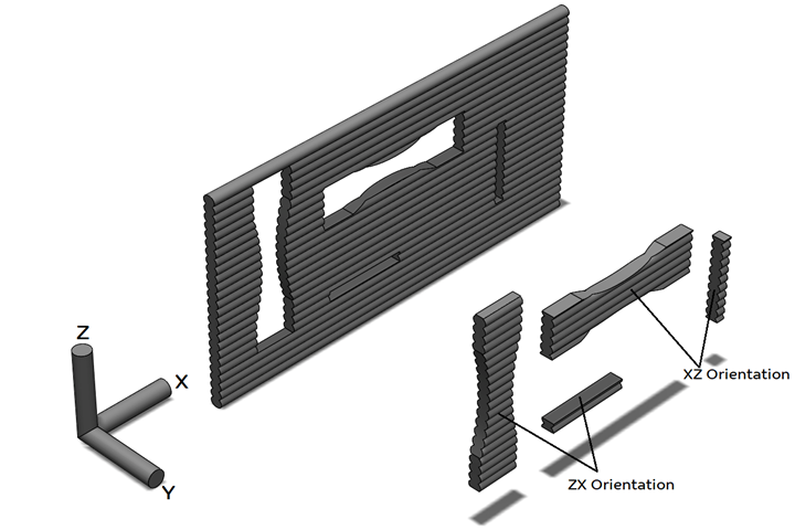
Figure 3: Diagram of tensile and flex samples cut from a hexagon panel in X and Z directions.
Photo Credit: SABIC
SABIC uses a continuous arc tensile bar geometry to avoid failures in the transition regions. The revised geometry of the arc tensile bar is shown in Figure 4.
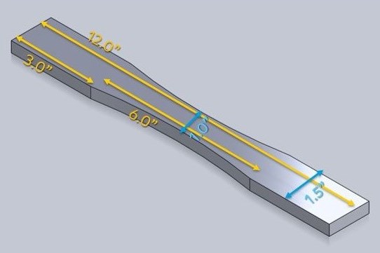
Figure 4: Arc tensile bar with dimensions. Photo Credit: SABIC
Tensile samples were tested using the ASTM D683 test method as a guideline. Flexural properties were measured using a three-point bend test following the ASTM D-790 method, using modified 3D printed samples described above.
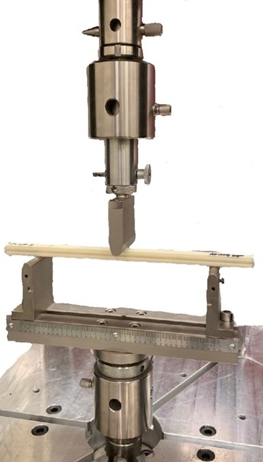
Figure 5: Flex sample in a three-point bend fixture.
Photo Credit: SABIC
Study Results
Printability Evaluation
All samples, from 0 to 100% regrind content, printed well, with a shiny and smooth surface appearance characteristic of virgin printed material. A minor exception was the 100% regrind sample: The printer’s rpm had to be slowed down to accommodate the sample’s higher flow characteristics. A hexagon test sample is typically printed at 100 rpm and the machine’s linear speed was adjusted to achieve the appropriate bead size. Extruder torque was tracked and averaged 95% for samples containing 0 to 75% regrind. The sample containing 100% regrind was printed at 80 rpm with a torque of 75%. This sample also had a little extra material drool from the nozzle compared to the other prints.
For all six prints, the extruded bead was steady, and all 100 layers were completed without collapsing or major defects, as shown in Figure 6. The straight, even layers indicate no issues with material flow.
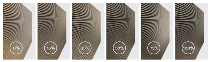
Figure 6: Comparison of hexagon prints, 0 to 100% regrind. Photo Credit: SABIC
Throughput Evaluation
The throughput test showed that material flow was relatively consistent among the six samples. The one exception related to the 400-rpm purge test rate. Only the 100% regrind sample was successful in completing the 400-rpm purge test. All other regrind percentage samples (0, 15, 25, 50 and 75) were only capable of completing purge test conditions up to the 300-rpm setting. After trying to purge the 0 and 15% regrind samples at the 400-rpm condition and torquing out the machine, the testers decided not to attempt the 25, 50 and 75% regrind samples. These results are shown in Table 1 and Figure 7.
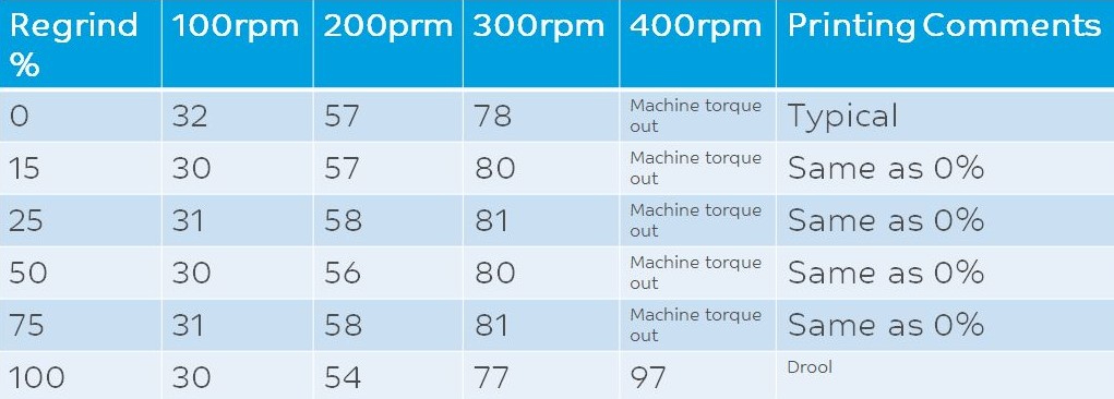
Table 1: Calculated throughput of each sample at 100, 200, 300 and 400 rpm.
Credit: SABIC
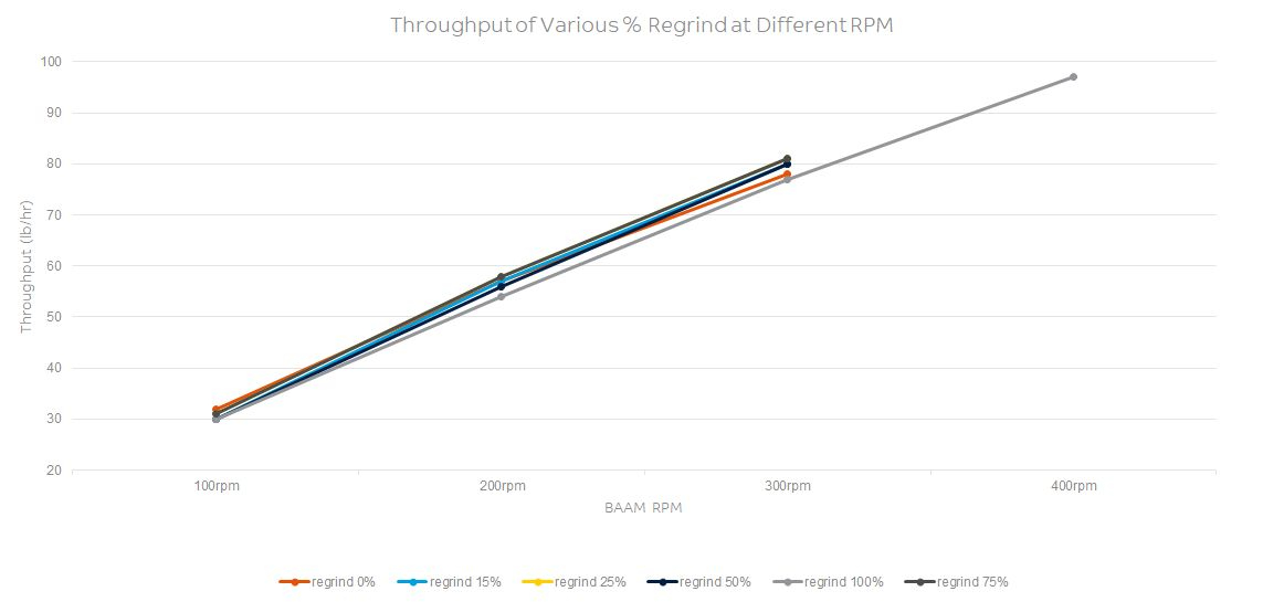
Figure 7: Plot of throughput for tested rpm at each regrind percent. Photo Credit: SABIC
Tensile and Flexural Evaluations
As expected, the tensile and flexural measurements showed a trend of decreased mechanical strength and slightly increased strain as the percentage of regrind in the sample became larger.
A comparison of the mechanical properties of the virgin material to the 100% regrind sample showed a 20% drop in tensile stress in the X direction stress and a 15% drop in tensile stress in the Z direction. Using the same comparison, virgin material versus 100% regrind sample, flexural stress performance showed a 14% drop in the X direction and a 12% drop in the Z direction. All other samples tested as expected, with values falling between 0 and 100% regrind. Results are shown in Figures 8 and 9 and Table 2.
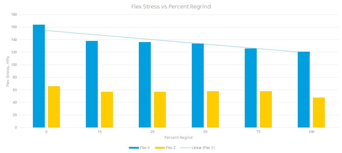
Figure 8: Chart of flex stress in the X and Z directions for each regrind level. with trend line.
Photo Credit: SABIC
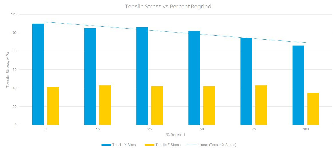
Figure 9: Chart of tensile stress in the X and Z directions for each regrind level, with trend line.
Photo Credit: SABIC
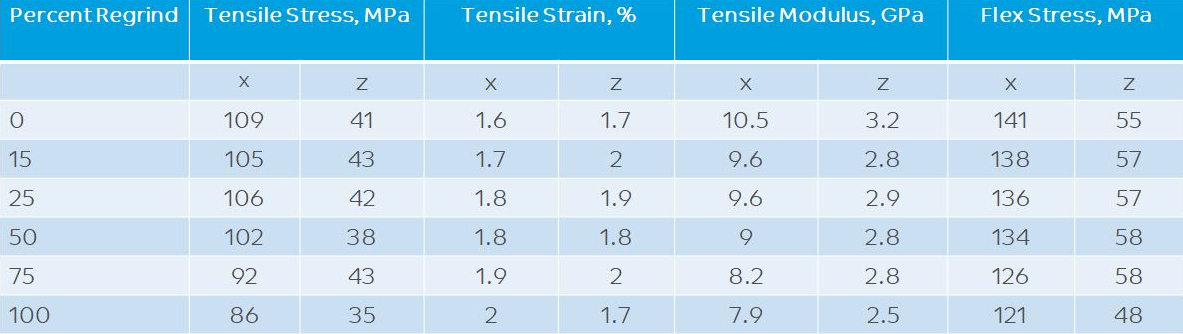
Table 2: Mechanical property results for each regrind level. Photo Credit: SABIC
Conclusions
Overall, this evaluation showed that the waste and scrap from LFAM has the potential to be reprocessed instead of being discarded in a landfill. The material samples containing up to 100% regrind printed without any processing issues. However, a mechanical performance drop was seen as more regrind was added to each sample. Following the testing, it was observed that there was approximately a 20% reduction in tensile stress in the X direction.
As material goes through compounding and extrusion into pellets and processing and reprocessing, it develops a cumulative heat history. Each additional heat history causes the polymer chains to break down further, reducing overall performance. In this study, the reground, pelletized material was added back into virgin material as a dry blend, thus eliminating the heat history needed to re-melt and pelletize a homogenous material.
Application performance requirements and any reduction in mechanical properties incurred by the use of regrind will dictate how and where the LFAM regrind material can be used. This study only looked at a single lot of regrind. Larger quantities should be tested to more accurately determine lot-to-lot variation, mechanical property changes and effects on LFAM printability.
With growing use of LFAM and increased printing of very large end-use parts and tools, the additive manufacturing industry needs to address the landfilling issue. This study is only the first step in showing that re-use of LFAM parts and scrap is feasible. Although there are end users with parts and scrap ready for potential re-use, gaps in the existing recycle value chain (specifically the process to collect and regrind parts and shavings and reprocess them into pellets) need to be filled before this process will be viable. A collective effort by the LFAM community, along with existing plastic recycling efforts, is necessary to find an economical method of collecting LFAM scrap and converting it into a pellet form that can be reused. This may require a different model or structure than what is available today.


Related Content

Sustainable Metal Powder Company Addresses Next Piece of Road Map: Renewable Energy
Continuum Powders, the material production arm of small-scale foundry technology company MolyWorks, has announced new partnerships aimed at further reducing the environmental impact of its metal powder production.
Read More
How Hybrid Tooling — Part 3D Printed, Part Metal Shell — Accelerates Product Development and Sustainability for PepsiCo
The consumer products giant used to wait weeks and spend thousands on each iteration of a prototype blow mold. Now, new blow molds are available in days and cost just a few hundred dollars.
Read More
6K Additive Partners With Incodema3D for Powder Supply, Recycling
6K Additive says its nickel alloy 625 powder surpassed every quality measure in tests performed by Incodema3D.
Read More
MolyWorks Streamlines Production With 3D Systems’ Direct Metal Printing Solution
MolyWorks, a California-based developer of a circular economy for metal, has integrated 3D Systems’ DMP Flex 350 into its manufacturing workflow, enabling it to be more agile and efficient, and expand its customer base.
Read MoreRead Next

The Results Are In: Autoclave Tooling and Large Format Additive Manufacturing
SABIC and the University of Dayton Research Institute studied large-format additive manufacturing (LFAM) for metal autoclave tooling. The results are promising.
Read More
Why “Recycled” Doesn’t Mean Inferior for 3D Printing Filament
GreenGate3D’s PET-G filament is made from recycled plastic, but that doesn’t diminish its quality. How a recycler found a new business opportunity in 3D printing, and how this success might point the way to a more effective recycling ecosystem.
Read More
Autonomous Underwater Vehicle With 3D Printed Hull: The Cool Parts Show #24
Our first episode of The Cool Parts Show from inside a 3D printer! Big Area Additive Manufacturing (BAAM) produces exterior components of a robot submarine and changes how this AUV is marketed.
Read More