
Validating and Qualifying
X-ray technology can validate the internal geometry of additively-manufactured parts in 3D without destroying the part.
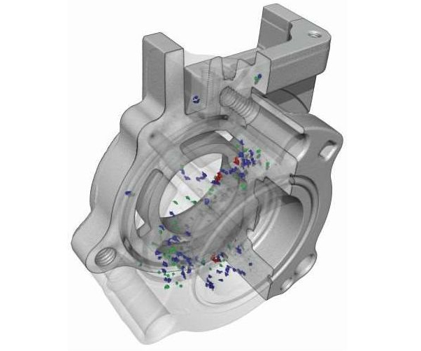
Internal porosity accumulation within an aluminum casting is identified and color coordinated by size using industrial computed tomography (CT) scanning equipment.
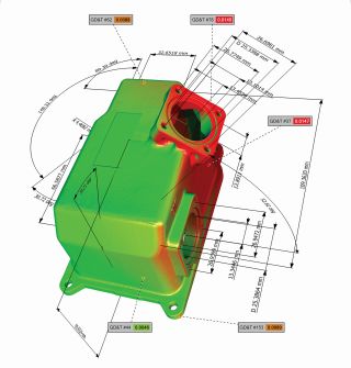
Internal and external part structure geometric dimensioning and tolerances (GD&T) points as well as varying wall thickness coordinated by color.
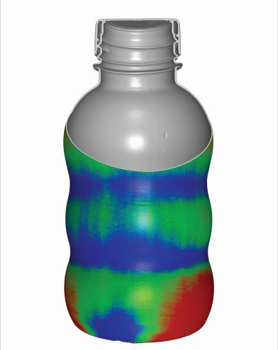
Plastic bottle depicting varying wall thickness determined by density and material distribution.
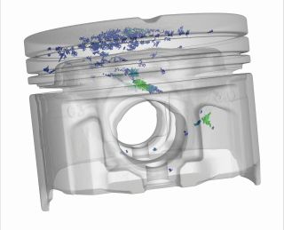
To identify void buildup, a boundary was created around the piston head and for each internal void within the part. Internal voids were then quantified by the volume of each pore and color coordinated according to size.


Measurement plays an integral role in the production cycle of 3D printed parts, so the need for testing these parts for validation grows. One approach is a nondestructive testing (NDT) method called industrial computed tomography (CT) scanning, which quickly and accurately validates the internal geometry of additively-manufactured parts in 3D without applying any external forces or pressure that might alter or warp the parts.
Applying CT Scanning in AM
Featured Content


Geometry in a limited-production, additive-manufactured or laser-sintered part occasionally requires validation for an integral part of an assembly. To confirm shape and size, industrial CT scan results are analyzed by creating a dataset and comparing it against a CAD file or GD&T blueprint. Industrial CT scanning also can identify wall thickness issues in the first printed part, so that the design or additive manufacturing process can be modified to ensure that the limited production run meets the intended design parameters.
Another useful feature of CT scanning is quick validation of the part to the CAD model to determine internal and external deviations from initial design. Industrial CT scanning is the most effective nondestructive method for authenticating the internal geometry to the CAD model in 3D.
The technology’s ability to retrieve both external and internal measurements on an additively manufactured part without destroying the part, also enables an industrial CT scan dataset to be used to develop first-article inspection and PPAP reports and to fulfill AS9102 requirements. Using traditional testing methods, a coordinate measuring machine (CMM), for example, the user is constricted by having to use touch probes to access part print points. With an industrial CT scan, geometric dimensioning and tolerances (GD&T) points are accessible from any angle in 3D. This nondestructive x-ray technology is also capable of identifying internal cracks, knit lines and porosity between the intersections of resins in multi-material printed parts.
Similar to the way in which geometry is validated, porosity is detected by analyzing the scanned results through CT’s ability to detect different material densities. Identifying these areas in preproduction allows for adjustment to machine parameters prior to the first saleable run. Any foreign material or inclusions can also be detected in the printed parts by locating varying densities in the scanned results.
As a reverse engineering tool, industrial CT is able to capture internal and external geometry for 3D printing, laser sintering and rapid prototyping applications. For additive manufacturing applications, the dataset is typically translated to a point-cloud/polygon-based file format such as STL, WRL, TXT and OBJ. With the point-cloud file, the user can either go directly to printing, or transport the file into a CAD suite and perform modifications to the dataset prior to printing. In a part’s design phase, an engineer will utilize multiple levels in CAD for dissimilar components for development, viewing and editing purposes. When data is exported from a CT scan all of the components are together on a single level.
Voids analysis, wall thickness analysis, fiber analysis and first-article inspection reports can all be assessed through one CT dataset, providing flexibility and options to meet virtually all testing needs.
Reviewing Costs and Benefits
When comparing an industrial CT scan to traditional methods of inspection, three main factors should be considered: cost, time and value. To evaluate voids or measure wall thickness using traditional methods, a part must be cut open and assessed manually. The overall manufacturing cost is doubled by default when parts are tested using these traditional methods, as the part is destroyed. Although these inspection methods themselves are relatively inexpensive, they require an increase in the time allocated for quality control and thereby boost production costs. With industrial CT scanning, inspected parts are available for use immediately after the testing process, thereby avoiding additional manufacturing costs and saving time on the total production cost of a single part.
When CMM inspection methods are used, the part becomes sectioned and no longer useable. For projects that require measuring 65 GD&T points or more with more than three parts, the cost of running a CMM increases. In measuring the same number of points using an industrial CT scan, a user can save time and up to 50 percent of the production cost for multiple parts.
Industrial CT scanning can play an integral role in the quality control process when it comes to inspecting small, highly complex, detailed additive-manufactured parts, whether they are plastic components, metal parts or mold components. This inspection method ensures that parts meet the requirements for fit, function and interchangeability. Industrial CT scanning can qualify additive manufactured parts quickly while reducing inspection costs, using the right technology, expert analytical support and scan data calibration to ensure accuracy.


Related Content

Aidro Becomes Leonardo Helicopters' Supplier for Aluminum Flight Parts
Aidro is one of two suppliers to receive the Declaration for Qualification of Process for Additive Layer Manufacturing with Leonardo.
Read More
Additive Manufacturing for Defense: Targeting Qualification
Targeting qualification in additive manufacturing for the defense industry means ensuring repeatability as well as reliability as there is much at stake, including human lives. Certain requirements therefore must be met by weapons systems used by the defense industry.
Read More
AIM3D Study Shows 3D Printing Ultem 9085 Pellets Offers Lower Cost, Higher Tensile Strength
The material qualification testing indicates many benefits of creating components with AIM3D’s ExAM 510 printer using the composite extrusion modeling process, which uses standard pellets rather than the more expensive filaments required by other platforms.
Read More
Inspection Method to Increase Confidence in Laser Powder Bed Fusion
Researchers developed a machine learning framework for identifying flaws in 3D printed products using sensor data gathered simultaneously with production, saving time and money while maintaining comparable accuracy to traditional post-inspection. The approach, developed in partnership with aerospace and defense company RTX, utilizes a machine learning algorithm trained on CT scans to identify flaws in printed products.
Read MoreRead Next

Inspect the Part As It Grows
The 2016 IAMA was awarded for a technology that monitors thermal radiation to map the internal consistency of a metal part as it is being made. The technology might point the way to an entirely new paradigm for inspection.
Read More
Real-Time, High-Res Monitoring of Structural Defects in Metal AM
A team at Argonne National Laboratory has, for the first time, captured below-surface measurements of laser-metal reactions.
Read More
Hybrid Additive Manufacturing Machine Tools Continue to Make Gains (Includes Video)
The hybrid machine tool is an idea that continues to advance. Two important developments of recent years expand the possibilities for this platform.
Read More