
3D Printing with Postprocessing in Mind
3D printing requires different finishing considerations than traditional manufacturing. One expert offers do’s and don’ts for approaching the finishing of additively manufactured parts.

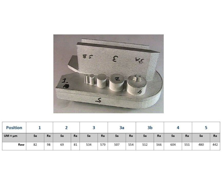
Figure 1 and Table 1: All images courtesy of Bel Air Finishing Corp. Table 1 displays surface measurements in microinches taken from six different positions on one 3D-printed part, pictured above. Special thanks to GKN Aerospace, Sintavia LLC and EOS North America.
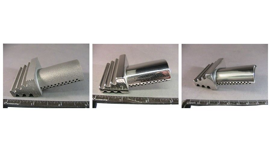
Figure 2: On the left, the first article of a sample air compressor blade as printed, and in the center, after a superpolish postprocessing operation with imperfections on the leading edge of the profile. On the right, a second article, after the feedback loop, with re-orientation of the build to avoid porosity after postprocessing.
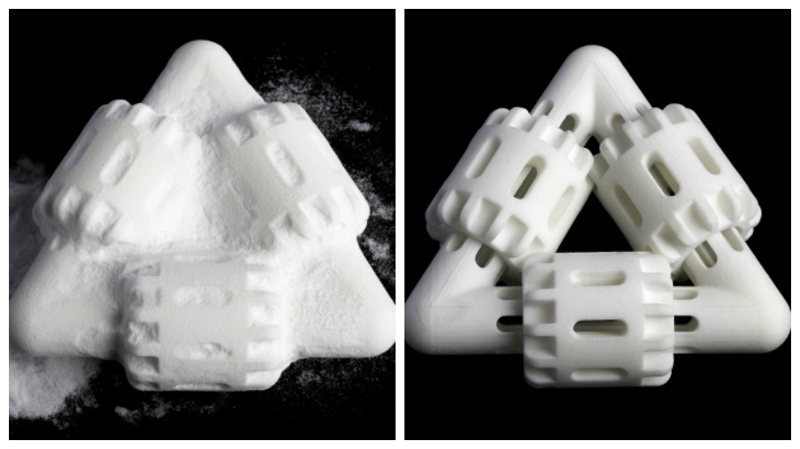
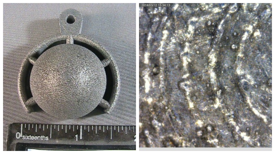
Figure 4: This image shows a metal 3D-printed part before postprocessing, magnified 200× on the right.
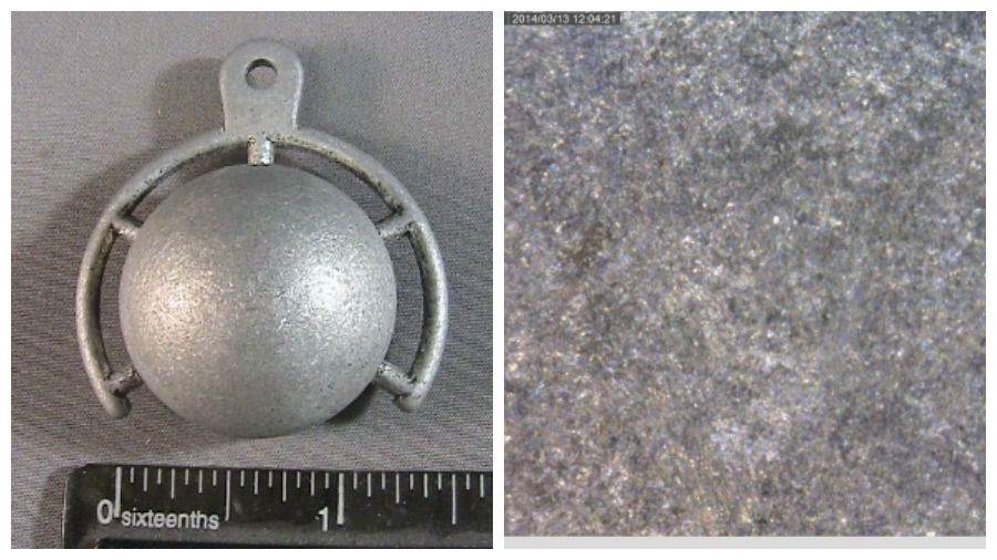
Figure 5: This image shows a metal 3D-printed part after wet grinding postprocessing, magnified 200× on the right.
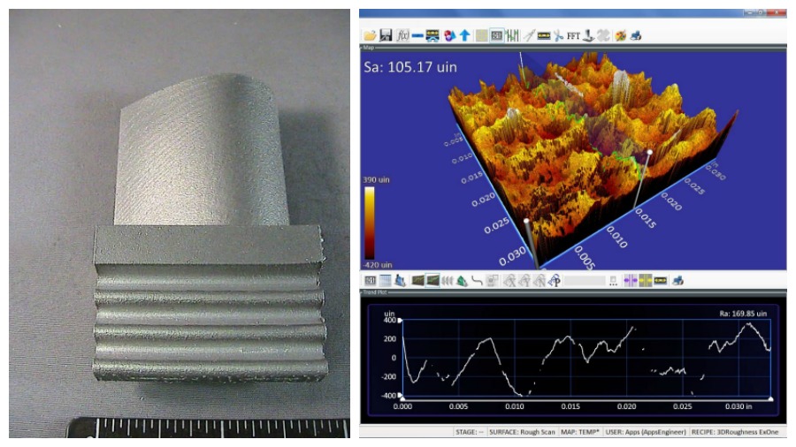
Figure 6: This figure shows the areal surface measurements (Sa 105 microinches) and linear measurements (Ra 169 microinches) and a topographical map of a metal 3D-printed part taken before postprocessing.
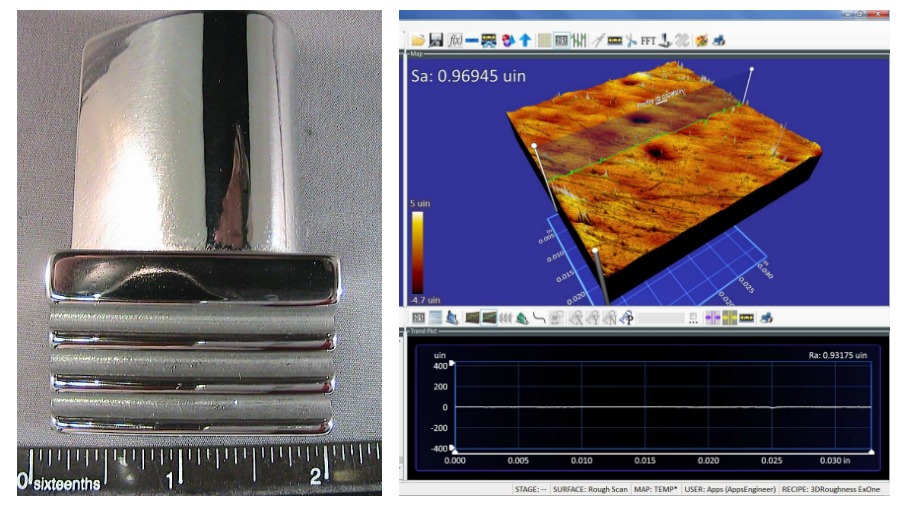
Figure 7: This figure shows the areal (Sa 0.96 microinches) and linear (Ra 0.93 microinches) measurements and a topographical map of a metal 3D-printed part after wet grinding and dry reverse drag postprocessing.
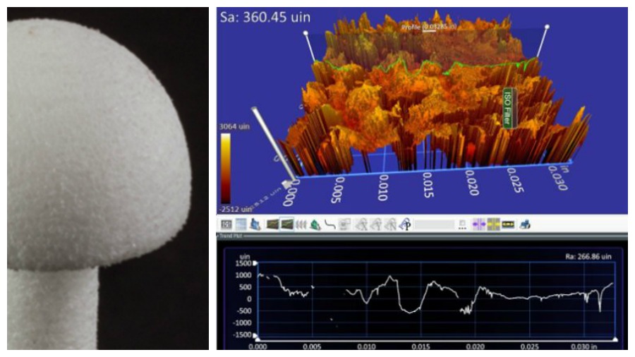
Figure 8: This figure shows the areal surface measurements (Sa 360 microinches) and linear measurement (Ra 266 microinches) and a topographical map of a plastic 3D-printed part before postprocessing.
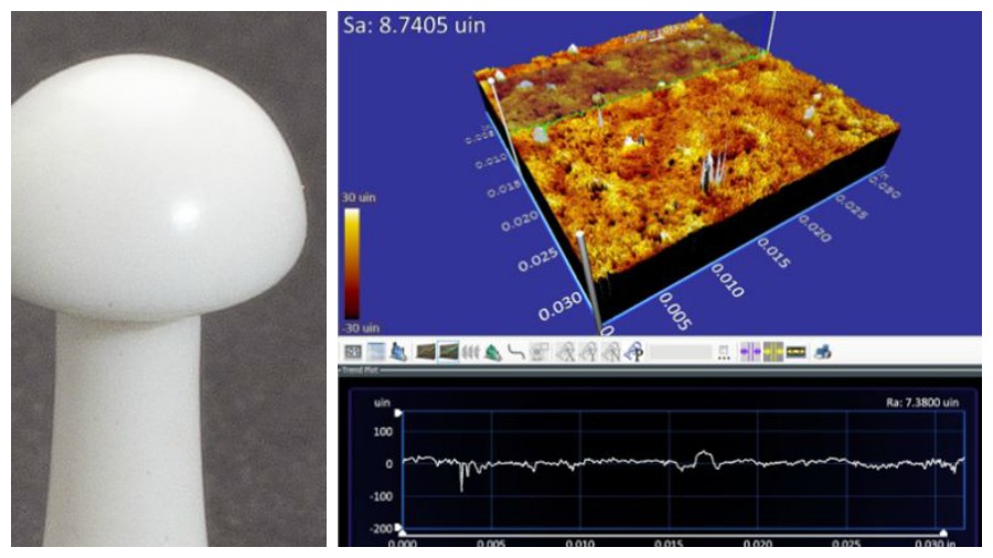
Figure 9: This figure shows the areal (Sa 9.6 microinches) and linear (Ra 7.3 microinches) measurements and a topographical map of a plastic 3D-printed part after wet grinding.
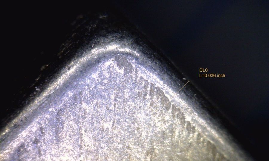
Figure 10: To avoid excess corner rounding, this edge berm, which is a form of masking, was designed in the build to allow for a sharp corner after the finishing process.
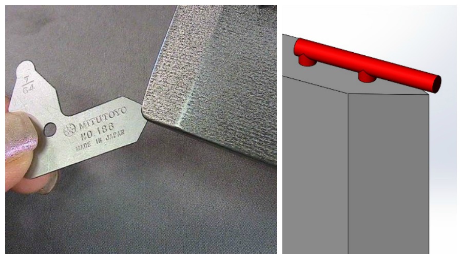
Figure 11: Mass finishing can also cause this degree of corner rounding on this first article print. A break off mask shown in red could have been built to avoid the rounding of the corner. This is the feedback loop used on the next build.
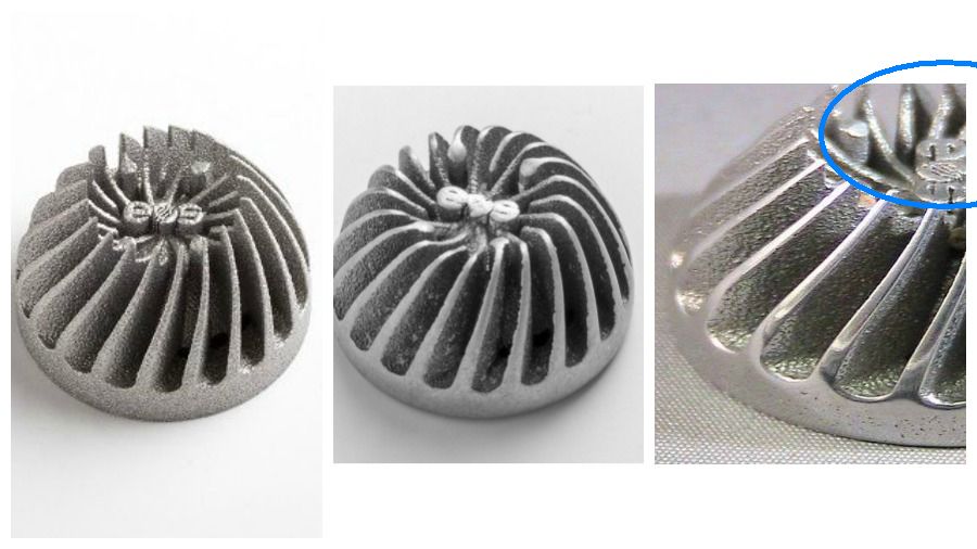
Figure 12: These three photos show a part produced in aluminide with the first article finishing and then the feedback loop of the design. Note the sharpness of the blade geometry in the left image. In the center, the sharpness of the blade geometry has been removed by postprocessing. After the feedback loop (right) the sharpness of the blade geometry was maintained by a simple masking (depicted in blue) prior to postprocessing.


Consider a traditionally manufactured part that involves three machining operations followed by brazing. The machined surfaces range between a roughness average (Ra) of 20 to 30 microinches and meet all functional industry requirements. Along comes 3D printing technology, and now that same part can be made in one integral piece directly from the printer. Sounds like a winner, right?
There is a problem, says Steven Alviti, president of Bel Air Finishing Supply of North Kingstown, Rhode Island. Despite their advantages, additively manufactured or 3D-printed parts present challenges when it comes to achieving a quality surface finish. These can stem from the method of printing or layering of material, the size and deviation of the layers, part orientation in the working envelope, material particle size range and its reaction to the AM process.


“Although the numerous benefits of AM are becoming more and more apparent, such as creating complex geometries with intricate detail and parts with complicated internal passages, the old adage ‘where you gain on one front, you may lose on another’ applies to this technology,” says Alviti. “The cost associated with all the benefits of AM is achieving a quality surface finish.”
Alviti explains that starting surface finishes of a metal or plastic 3D-printed part can be recorded as good as Ra 100 microinches or as gross as Ra 1,000 microinches, and this range of finish can vary tremendously even on a single part (see Table 1 and Figure 1, above).
He believes that this fact alone makes the required surface finish much more difficult to achieve and begs the following questions: Is it possible to make this part’s surfaces conform to its function? That is, does it need to be friction free, or does it have a press fit specification, a surface Ra, root mean square (RMS) or some other mechanical specification? If so, how much will the printed part’s cost increase? How will that compare with the conventional part price? When the printer, printing process and part finishing are factored in, how does this compare to the cost of making a part using conventional manufacturing methods?
Rules to Live By
When 3D printing is the way to go, Alviti has a few recommendations for improving 3D part surface finish.
Do understand there is no one technology that suits all 3D printing finishing applications. The surface of the printed part is directly affected by the type of printer, the printing technology and the material grain size. Finishing technologies must be mixed and matched with each individual part design based on material, printing techniques and part geometry. It is also important to note that multiple techniques can be used on the same part.
Don’t design a part with a conventional manufacturing thought process. Chances are that there will be dimensional challenges and/or surface finishing problems when a printed part is integrated into its functional assembly. Corner, angle and surface geometries will probably need to be built in an unconventional manner. Loss of material at a surface, other than a corner, can range between 0.001 to 0.005 inch.
Don’t design a part with the 3D hype mentality. The hype suggests that you can take a five-piece assembly and turn it into a one-shot build with your printer. But considering surface finish requirements and understanding that conventional finishing methods will not be applicable may make it necessary to break down and simplify the design. For example, a one-shot build could be divided into a two-part build with a single assembly. This may allow for standard finishing techniques to handle dimensional requirements and still have a more efficient process of production.
Do use a technique that Alviti refers to as the feedback loop. Using expert finishing recommendations and one of the three methods shown in Figure 2, print a first article part of a design. Then evaluate the dimensional tolerance, surface finish and any lost geometry. Next, feed this information back to the build design. This may entail adding extra material and sharper corners, breaking the design into multiple parts, or even adding what is called a mask. This is a breakaway structure that can protect a particular part geometry from extra material removal.
Do define your surface finish requirements before you choose your 3D printing method, technology and part design. A part prints with many different surfaces finishes, depending on its orientation with relation to the build plate, the position in the box and its own geometry. So, for the best surface finish, take into account the printing method and critical surfaces in orienting the part. Keep in mind that the speed of a build and the resulting surface finish are at opposite ends of the spectrum. For example, the lower the starting as-printed Ra, the more likely and faster you will achieve the required surface specification.
Do understand post-processing finishing techniques.
- Make cleaning part of your finishing process once the part is removed from the build box. If using powder-bed technology, clean the parts directly from the plastic or metal powder beds with waterjet techniques that not only clean in a dust-proof atmosphere, but also improve the surface finish by up to 50 percent during the same operation, according to Alviti. Figure 3 shows removal of the excess material of a nylon part with a greatly improved Ra after waterjet cleaning.
- Use wet grinding for the gross surface smoothing operation. Wet grinding is performed by a machine that uses an abrasive media to grind the surface of a part while constantly flushing the total mass of parts and media with water and grinding fluid. The three most popular techniques use high energy to enhance the finishing process:
- Centrifugal disc finishing (FMSL). Tumbling machines use extra energy (5 to 10 G-force) to grind the parts with the correct abrasive to match the requirements.
- Centrifugal barrel finishing (CB). This method is the same as FMSL with the exception of a closed barrel and even greater energy (5 to 30 G-force).
- Reverse drag finishing (FMRD). This is a liquefied grinding slurry passing over the surfaces to be finished.
These techniques are used to bring the gross Ra surfaces of 3D-printed parts down to the finer Ra surfaces similar to machining or polishing (see Figures 4 through 9).
- Note that the nature of wet grinding and other mechanical surface finishing method, requires material removal. Again, it is important to know that the worse the surface finish a part has, the more material removal is required to achieve an even and quality surface finish. The material removal effects must be fed back into the build geometry and orientation to compensate for the loss of geometry to the edges and other intricate surfaces. For example, add masking in to the build to protect an edge or a particular critical dimension of the part, or add material onto corners to maintain their sharpness (see Figures 10, 11 and 12).
Do take the time to understand and experiment with whatever finishing methods you have available. Have some specifically designed shapes built in several machine technologies and then have the surfaces finished by conventional methods to analyze the results and limitations before you purchase or before you design a part.
.png;maxWidth=300;quality=90;format=webp)


Related Content

AM 101: What Is Hot Isostatic Pressing (HIP)? (Includes Video)
Hot isostatic pressing has long been used for metal castings, but is now being applied as a valuable method for closing porosity in metal 3D printed parts.
Read More
Postprocessing Steps and Costs for Metal 3D Printing
When your metal part is done 3D printing, you just pull it out of the machine and start using it, right? Not exactly.
Read More
Why AM Leads to Internal Production for Collins Aerospace (Includes Video)
A new Charlotte-area center will provide additive manufacturing expertise and production capacity for Collins business units based across the country, allowing the company to guard proprietary design and process details that are often part of AM.
Read More
3D Printed Cutting Tool for Large Transmission Part: The Cool Parts Show Bonus
A boring tool that was once 30 kg challenged the performance of the machining center using it. The replacement tool is 11.5 kg, and more efficient as well, thanks to generative design.
Read MoreRead Next

Can My Machine Tool Access My Support Structures?
Analyzing the machinability of support structures opens a new way of thinking about optimal build orientation.
Read More
The Post-Production Challenge for Additive Manufacturing
The benefits of controlling postprocessing operations for additively produced parts reach beyond cost.
Read More
3D Printing Brings Sustainability, Accessibility to Glass Manufacturing
Australian startup Maple Glass Printing has developed a process for extruding glass into artwork, lab implements and architectural elements. Along the way, the company has also found more efficient ways of recycling this material.
Read More