
By Mapping Layer Height, Velo3D Shows Where Part Is Distorting (Includes Video)
Height measurement reveals what layers and what part features are potential problem areas in the metal additive manufacturing build. Watch the video to see how software provides insights from layer height data.


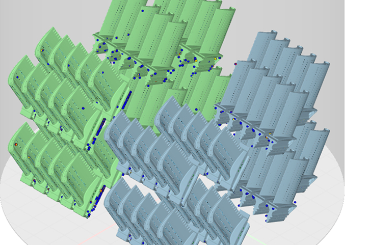
Layer height data projected onto a 3D model reveals the points at which the incomplete part distorted as it was being 3D printed. This is potentially useful insight for improving the design of the part, as described in the article and video below. All images courtesy of Velo3D.
On a laser powder bed additive manufacturing (AM) machine, the laser parameters alone don’t determine the outcome of the part. The powder bed also matters. Precisely tuned laser parameters assume a specific bed layer height — that is, a specific amount of material to absorb the energy of the beam. Waves, furrows or other imperfections in the flatness of the powder layer inherently mean there is more material piled up in some areas of the bed, less in others. Too much powder in a given spot, and that region might not fully melt. Too little, and rather than melting the powder might vaporize.
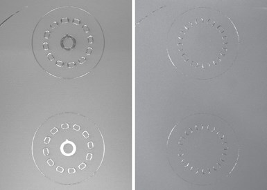
Here is a given layer (it happens to be layer 600 of this particular AM build) before and after powder recoating. After recoating, the powder bed is not perfectly flat. Details of the part still extend above it. This is normal; it poses a problem only if an unexpected distortion causes a part detail to extend farther than expected above the powder bed.
Velo3D’s laser powder bed metal AM system, Sapphire, includes sensors for mapping powder bed flatness at every layer throughout the build. Initially these sensors helped the company understand and refine the performance of the machine as it was being developed. Now the sensors are still in place, and they provide for a “Height Mapper” capability that is part of the company’s Assure quality assurance software, a recent addition to its portfolio that aggregates sensing data throughout the build to provide a QA record. As company VP Zach Murphree recently explained to me, the height mapping data is also being used to construct digital models of parts offering insight into the build that was never possible before. With height-map data layers combined into a 3D form within Velo3D’s Flow software for modeling and build preparation, a designer can see what details of the part distorted the most from the part’s nominal form throughout the course of the build. This is insight likely to be valuable for redesigning the part for subsequent builds, and it might mean fewer 3D printing iterations before getting to the design that is final, Murphree says.


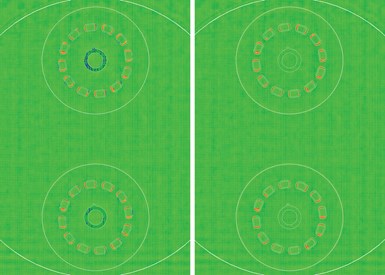
Here is that same layer, as mapped using the layer height measurement capability. Velo3D's sensors and system map each layer to a pitch of 100 microns in X and Y and a resolution of 15 microns in Z.
Either a distortion of the part or a disruption of the layer recoating might account for why the powder bed is not flat at any given layer. The Sapphire machine uses noncontact recoating, not a direct-contact blade, so damage to the blade is not a potential cause of layer inconsistency. But Velo3D still found effects it needed to control for the sake of layer flatness during its machine development. Inconsistencies in early test parts were traced to inconsistent layer flatness, which was discovered to be the result of pressure change within the chamber due to a valve opening. With effects such as this now identified and controlled, the likely cause of an inconsistent layer height today is a warped part extending some feature detail above the bed.
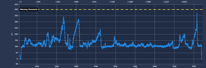
Height Mapper, within the Assure software, tracks layer heights in order to validate that the height deviation of each layer of a build remained within acceptable tolerance.
The machine can respond to this, Murphree says. Any individual layer measured to be departing too far from consistent flatness will trigger Sapphire’s control to recoat that layer. (If that doesn’t fix the problem, the machine can be programmed to stop and wait.) When a build is done, the height mapping contributes to that part’s data record. In Assure, the Height Mapper data displays as a graph, layer by layer, of how near or far the build came to surpassing its maximum acceptable deviation.
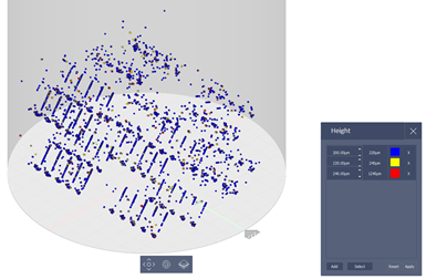
Here is the same 3D model from the beginning of the article, with the key added and the parts removed so only the height deviation is visible. Using height measurement data in this way offers a new way to visualize the effectiveness of the AM build.
The next-level use of this data is one the company is just starting to develop and share with customers. This is layer-height data, which is at essence part-deviation data, as a tool for visualizing the build behavior of the part. Details of the part are color-coded in this model according to how far they departed from the nominal part geometry as the part was taking shape. Even for a successful build, this visualization makes clear the danger areas where the build is most prone to break specification during production. The designer can use this model as a guide to modify the part, strengthening it in these distorting areas, so the production build will be more repeatable.
Murphree recently spoke with me about Height Mapper and 3D modeling the layer-height data. Here he is showing me these capabilities:


.png;maxWidth=300;quality=90;format=webp)


Related Content

To Scale Additive Manufacturing, Separate Design and Production
Spokbee’s online marketplace is designed to ease the launch and sale of customizable, 3D printed products. Its flexibility comes from cloud-based CAD and a distributed network of service bureaus for production.
Read More
Lightweight Components: A Paradox When Machining
Today’s computer software can just as easily generate lightweight shapes for subtractive processes as it can for additive ones, but it increases cost and waste to make them.
Read More
Additive Manufacturing Production at Scale Reveals the Technology's Next Challenges: AM Radio #28
Seemingly small issues in 3D printing are becoming larger problems that need solutions as manufacturers advance into ongoing production and higher quantities with AM. Stephanie Hendrixson and Peter Zelinski discuss 6 of these challenges on AM Radio.
Read More
Implicit Modeling for Additive Manufacturing
Some software tools now use this modeling strategy as opposed to explicit methods of representing geometry. Here’s how it works, and why it matters for additive manufacturing.
Read MoreRead Next

Siemens Additive Manufacturing Simulation Solution Predicts Distortions
Siemens’ additive manufacturing process simulation solution enables manufacturers to design and print useful parts at scale.
Read More
Video: The Impact of Part Orientation on Cost and Build Time in AM
A different build orientation might mean fewer layers and less support structure, though the part might need to be redesigned to take advantage of this different orientation.
Read More
Support Structures Hold Down Productivity, Says Velo3D
A build example involving an aircraft bracket illustrates the production rate increase resulting from more parts per build plus the elimination of support removal. A new system for quality monitoring aids production as well.
Read More