
Simulation Supports Custom 3D-Printed Knife
Build simulation revealed that distortion was likely to occur in this custom chef’s knife. Thermal shrouding and an unusual support structure were used to counter it.
.jpg;width=70;height=70;mode=crop;format=webp)
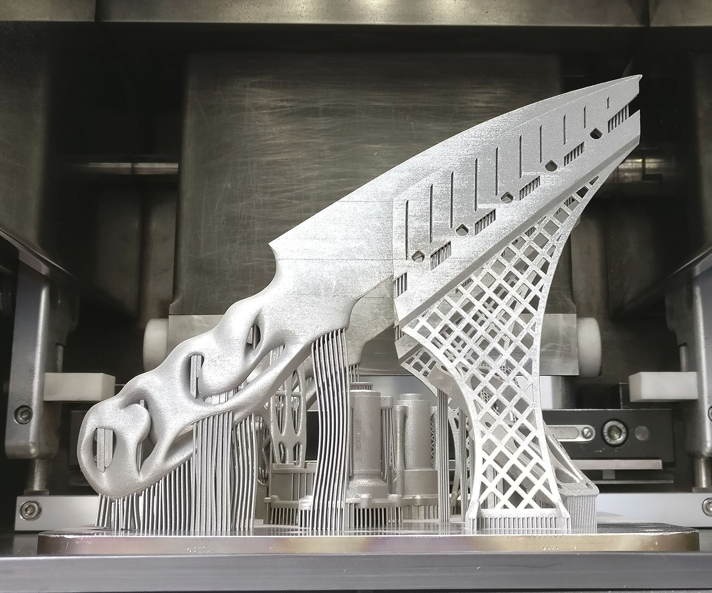
This custom chef’s knife was 3D-printed in titanium at the University of Sheffield Advanced Manufacturing Research Centre (AMRC). The difficult portion was not 3D printing the custom grip, but the long, thin blade.
Source: AMRC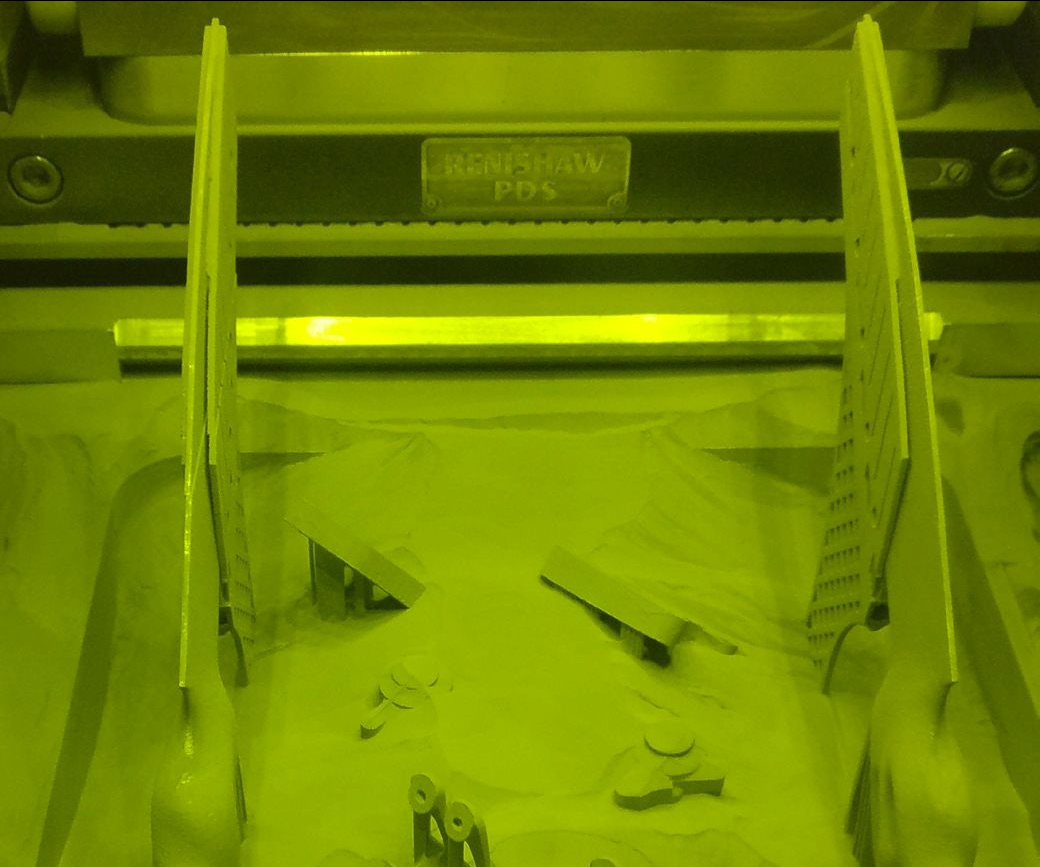
To counter possible distortion, AMRC engineers designed noncontact thermal shrouding, the wall of material that follows along the blade but does not touch it. The shroud prevents the blade from cooling too quickly, avoiding the creation of residual stresses.
Source: AMRC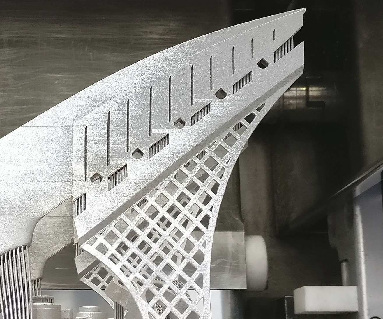
Vertical slits in the thermal shroud were used to break up the laser scan pattern to keep the shroud itself from distorting. The teardrop- and parallelogram-shaped holes are designed to accommodate a chisel to aid in removing the shroud during postprocessing. The optimized support structure that holds up the shroud and blade was created with Creo Parametric CAD software.
Source: AMRC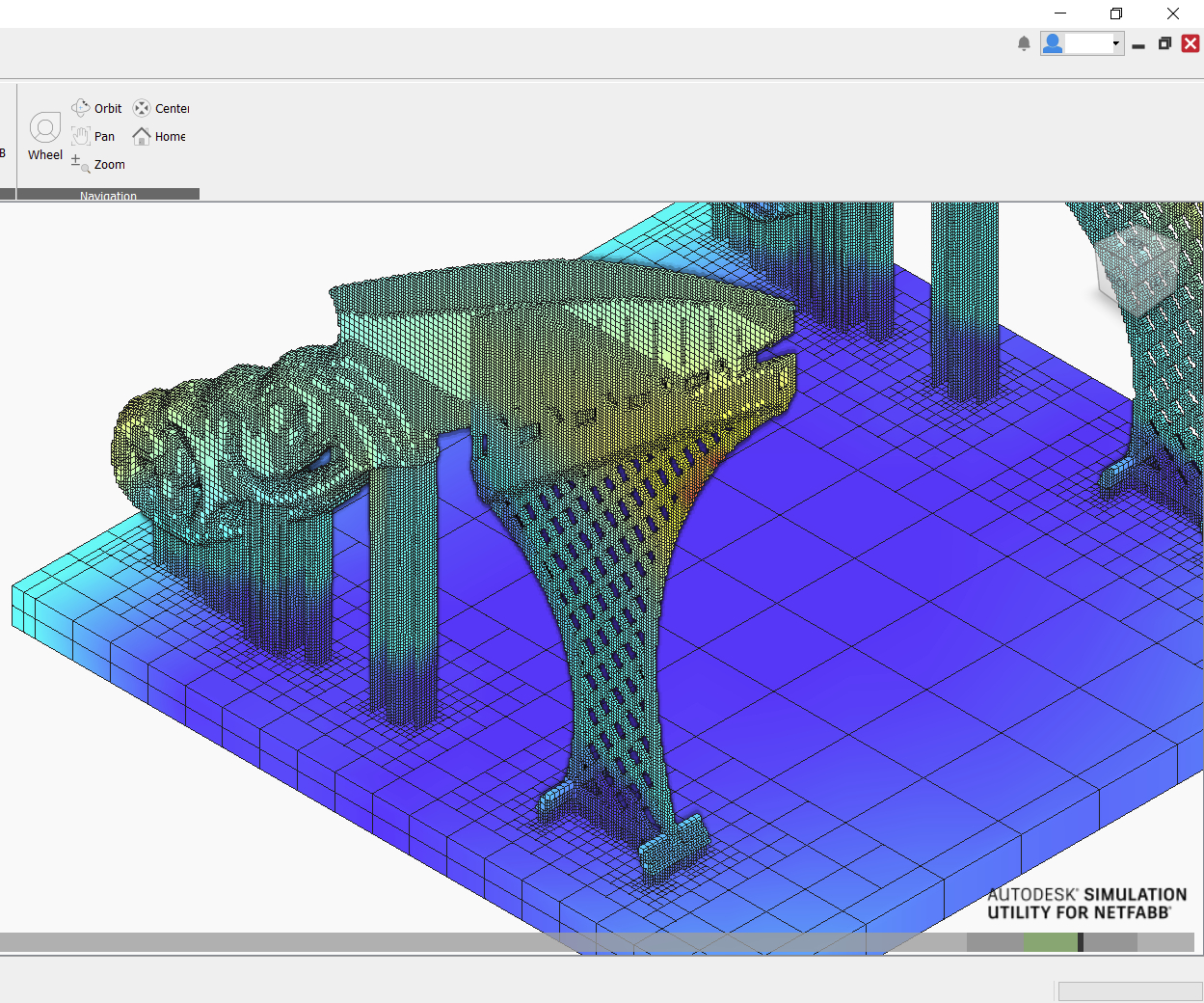
AMRC engineers used the Simulation Utility in Autodesk Netfabb to simulate 3D printing the knife in a Renishaw AM250 selective laser melting (SLM) system. Initial simulations showed a strong likelihood of distortion along the blade, but the addition of a noncontact thermal shroud and parametric support structure greatly reduced this risk.
Source: AMRC


Compared to jet fuel nozzles and mold tooling with complex internal channels, 3D-printing a custom chef’s knife might seem easy. This type of bespoke product is exactly the sort of thing that is understood to be ideal for 3D printing — a single, one-off object that can be made to perfectly suit its user.
In truth, when engineers at the University of Sheffield Advanced Manufacturing Research Centre (AMRC) set out to print such a knife, they found that it wasn’t so easy after all. The difficulty did not come from the customized geometry of the handle, which was reverse-engineered to precisely fit the grip of the chef who will use it and features a twisting, open design. Instead, the difficulty came from the most functional part of the knife: its blade. This long, thin piece of metal required the use of build optimization software, thermal shrouding strategies and a specialized support structure to ensure that it would 3D print correctly the first time. According to Luke Hill, project engineer at the AMRC, the team was challenged to apply its design skills in a different way than one typically thinks about design for additive manufacturing (DFAM). Rather than focusing on the part to be made, engineers turned their attention to what might otherwise be incidental parts of the process.


Hand-Crafted Meets Reverse-Engineered
The idea to 3D print a custom knife was inspired by a very different approach to custom cutlery. Working with Stuart Mitchell, a Sheffield-based knife maker, the AMRC created a project to demonstrate how 3D printing might be applied for a small business. The project was the subject of “Digital Mesters: Advanced Manufacturing for 21st Century Knives,” an exhibition at the annual Festival of the Mind held at the University of Sheffield. (Find the film showcased at the festival here.)
For the project, Mitchell handcrafted a chef’s knife as he normally would, using a stainless steel blade and custom handle with input from the chef. Simultaneously, AMRC engineers pursued an additively manufactured knife, beginning with a clay mold of the chef’s hand. The mold was scanned, and the resulting cloud mesh was converted into CAD to be used as the basis for the outer topology of the handle; to showcase the capabilities of metal 3D printing, the team removed material from within this outer skin, creating a twisting, open handle. After 3D-printing a prototype with an FDM 3D printer for look and feel, the AMRC team moved into build preparation and simulation.
Simulate Before 3D Printing
AM build simulation is a newer step for the engineering team at the AMRC, but one it has been exploring heavily over the past year or so.
“Typically the workflow would be using our knowledge and our experience to look for problems before going to print,” Hill says. “However, with the new workflow we’ve been working out, we now run the CAD model through a simulation to try and understand how it’s going to print before we put it through the printing process. Simulation is a fast process — that is, it’s faster than doing a physical AM print — and considerably cheaper, too.”
The AM knife was designed to be 3D printed from a titanium alloy on a Renishaw AM250 selective laser melting (SLM) system. The AMRC team used the Simulation Utility within Autodesk Netfabb to simulate the build. This is the team’s preferred simulation tool, Hill says, because of its speed and scalability. Netfabb allows users to adjust the voxel geometry and mesh resolution, meaning that low-fidelity simulations can be run quickly, perhaps in under an hour for small design changes, while high-resolution simulations that take longer are also supported.
The Challenges of 3D Printing a Knife
The build simulation showed that, with the selected orientation and automated support geometries, the titanium knife blade was likely to bend during the print. The thin structure would cool too quickly, leaving residual stresses that could cause distortion or even cracking to occur.
Fixing this problem meant rethinking the design of the build overall. Abdul Haque, another AMRC project engineer, created a solution by adding material to the build — not to the knife blade itself, but just to either side. This thermal shrouding does not even make contact with the blade — it is separated from the blade by a gap of less than 1 mm — but its proximity allows it to slow down the blade’s cooling rate. “If we can control the cooling rate, we can control the build-up of residual stress, and we can therefore control distortion,” Hill says.
Thermal Shrouding and Supports — And Their Challenges
But introducing the shrouding also introduced added difficulties, because the added material would need to be supported during the build and then removed afterward. This second problem was more easily solved, using access gaps in the shroud to accommodate a chisel during postprocessing. The support strategy, however, was more challenging. Standard, automated support strategies were not an option, Hill says, because the structures under the shroud and blade needed to help prevent distortion, not merely hold the material up.
“We’ll generally use the support geometries that are available to us in the additive manufacturing support processor — tree-type supports, pin-type supports, block-type supports,” Hill says. “However, at the moment the build processors we use are basically looking only at the geometric features and angles involved. There’s obviously more to it than that. It’s a thermomechanical process, so looking at the geometry alone doesn’t always tell the whole story. Scenarios like this where you have this likelihood of distortion at a relatively high point in the build create a slightly more complex set of problems.”
Rather than use a suggested support strategy or manually tweaking one to support the blade and shroud, the team used Creo Parametric CAD software from PTC to design a unique structure. The supports beneath the knife and shroud were optimized with this tool to prevent buckling as well as distortion. When the team ran this new build through the Simulation Utility (in a high-fidelity simulation that took about 5 hours), it showed a greatly reduced risk of distortion.
“If we hadn’t got the suggestion of high-level distortion from the simulation package, the print might not have been good enough the first time.”
The custom knife was printed successfully in one build without cracking or distorting out of tolerance, a feat that would likely not have been possible without the revelations of the initial simulation and subsequent use of thermal shrouding with optimized support structures. After postprocessing to remove the supports and thermal shroud, the 3D printed knife was delivered to Mitchell’s workshop for grinding to add the cutting edge.
“If we hadn’t got the suggestion of high-level distortion from the simulation package, the print might not have been good enough the first time,” Hill says. “Instead, we were able to go ahead with the print with the confidence that we wouldn't get the heavy distortion that we would have likely obtained if we had used the standard support geometry without the shroud.”
The experience working on this knife has helped convince Hill that optimization should have a role in 3D printing beyond part design. “Some of the AM build simulation packages are now using simulation to optimize support structures,” he says. “They’re trying to understand where the distortion is going to occur in the part, and then add more supports in those specific regions so you can keep the part pinned down to its nominal position. I think this is the next step for simulation packages, to get more in-depth with the analysis of where support material is used.”


Related Content

8 Cool Parts From RAPID+TCT 2022: The Cool Parts Show #46
AM parts for applications from automotive to aircraft to furniture, in materials including ceramic, foam, metal and copper-coated polymer.
Read More
Additive Manufacturing Production at Scale Reveals the Technology's Next Challenges: AM Radio #28
Seemingly small issues in 3D printing are becoming larger problems that need solutions as manufacturers advance into ongoing production and higher quantities with AM. Stephanie Hendrixson and Peter Zelinski discuss 6 of these challenges on AM Radio.
Read More
Flexible Bellows Made Through Metal 3D Printing: The Cool Parts Show #64
Can laser powder bed fusion create metal parts with controlled flexibility? We explore an example in this episode of The Cool Parts Show.
Read More
Velo3D Founder on the 3 Biggest Challenges of 3D Printing Metal Parts
Velo3D CEO and founder Benny Buller offers this perspective on cost, qualification and ease of development as they apply to the progress of AM adoption in the future.
Read MoreRead Next

A Three-Piece Toolset to Minimize Metal Additive Build Failures (Includes Video)
Three separate software tools from Siemens attempt to control some of the most challenging variables within metal AM: build orientation, distortion and deposition paths. Part of software video series.
Read More
Why GM’s Electric Future Is Also an Additive Future
Production capacity isn’t the only reason that additive has been slow to make inroads into the automotive industry. There is a larger barrier to entry—one that General Motors and Autodesk are working to overcome.
Read More
4 Ways the Education and Training Challenge Is Different for Additive Manufacturing
The advance of additive manufacturing means we need more professionals educated in AM technology.
Read More