
Shop Controls Its Own Destiny
Waiting sometimes 12 weeks for delivery of aluminum castings was a production bottleneck for this Colorado aerospace component manufacturer. Using a novel combination of solids modeling software, verification and stereolithography, the company managed to reduce lead times by 25 percent. This approach may be one your shop can use as well.

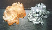
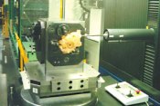
Side by side the rapid prototype model is geometrically identical to the casting. Machining the plastic gives the shop low risk debugging of NC programs. Likewise for inspection, the CMM program can be proved out prior to the delivery of the actual castings.
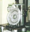
The shop is organized around manufacturing cells. This has improved throughput significantly by reducing work in process. Several of the cells have their own CMM for inspection.
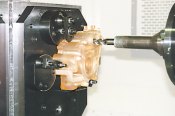
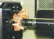
Using a part created by rapid prototyping allows this aerospace part producer to prove out and debug programs while waiting for delivery of aluminum castings. This process innovation provides significant time savings for this deadline manufacturer.
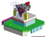
Unigraphics Solutions solid modeling software is used exclusively by Hamilton Sundstrand's design house in Rockford, Illinois. Concurrent engineering is used between the Grand Junction shop and the design engineers. Two files are created for a part: one shows the part as machined and the other shows the part as cast. The second STL file is sent to the foundry for castings and to 3D Systems for manufacture of the model.
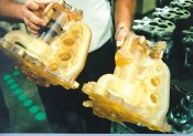
Generally, the shop orders three copies of a rapid prototype model. The model on the right represents the part as cast. The part on the left has been machined. Notice the difference in the bores.
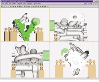
A final program check is performed using Vericut software. This package makes sure interference from fixtures and the machine is eliminated from the program.

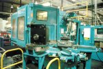
Mike Sneddon, senior manufacturing engineer, stands next to one of Hamilton Sundstrand's auxiliary power units (APU). The Grand Junction machine shop manufactures prismatic castings and round parts used in these units.
Share
Read Next


There's no question that advances in software technology are impacting metalworking across the board. Generally, however, application of the power of the computer to cutting metal is confined to the upstream side of the process.
Software that enables shops to visualize a design using solids, fixture a workpiece, and verify the cutting and interference points has existed for a while. Usually these software steps reside off the shop floor in the domain of manufacturing and production engineers. These are increasingly powerful tools for getting a shop ready to cut metal.


But regardless of how well the manufacturing process is conceived in software, there is almost always additional work to be done when the workpiece blank is mounted on the machine tool and the first cutter moves in for the kill. We visited a company that has devised a method to bridge the gap between computer generated machining and first article creation.
It has managed to insert an intermediary step that takes a real part, made using stereolithography or rapid prototyping, from which accurate prove out of the process can be done without risking tooling or workpiece blanks. Moreover, this intermediate step is performed using what was previously dead-time spent waiting for delivery of castings.
Who Are These Guys?
Hamilton Sundstrand (Grand Junction, Colorado) is a manufacturing plant for the United Technologies Company. Among the many parts this shop manufactures for use in auxiliary power units (APU) are prismatic castings. About 70 percent of the prismatic parts manufactured are aluminum.
Auxiliary power units are used in aircraft to maintain environmental and avionics when the plane is on the ground. These units are also a source of emergency power should the aircraft's main system fail in flight.
The shop employs 270 people and is set up using cellular manufacturing. Generally the work cube for this shop is about two feet. The cells are self contained, and most even have their own CMM for measuring workpieces. Since we're talking aerospace components, there's much measuring and documenting that must be done.
Like many captive machine shops, Hamilton Sundstrand is among the last stops for new product development components. After all the designing and tweaking are finished, the machine shop is free to make the part. Unfortunately, the shop is usually where all of the upstream lead-time losses come home to roost. It was just such a scenario that drove manufacturing engineers Mike Sneddon and Dave Leach to devise and implement a unique process to condense the shop's manufacturing lead-time.
First: Let There Be Cells
Like most shops, Hamilton Sundstrand is constantly looking for ways to wring out throughput time from the manufacturing process. That's why the shop is set up in manufacturing cells.
Each cell acts as a self-contained shop. These cells are comprised of turning centers and machining centers, machining centers only, grinders, and even lapping. The idea is to complete a component within each cell. So from a throughput perspective, the cellular arrangement has reduced work in process significantly.
Plastic!
Most of Hamilton Sundstrand's prismatic parts are machined from aluminum castings. Design for the castings comes from headquarters in Rockford, Illinois. "While we practiced concurrent engineering between the design team in Rockford and our manufacturing team here in Grand Junction," says Mr. Sneddon, "a real bottleneck for throughput was the lead time from finished design to having a casting in our hands to machine. This lead time could be as much as 12 weeks. Only upon receipt of the casting could we then begin to prove out part programs, fixturing and inspection routines. Sure, we had everything relating to the job in the computer, but a real part is different than a model."
That's when the shop hit on the idea of making a real part before the castings were delivered. "The impetus to find a better way came from a job for one of the leading aircraft engine builders," recalls Mr. Sneddon. "We were time compressed to the wall on this job. Our casting order was pushed out 9 to 10 weeks, which left us with 6 to 8 weeks to debug programming for the machines, CMMs and line up anodizing and coating of the finished parts. Usually we had twice that much time. We simply couldn't make the schedule. We had to find another way."
The idea was to make a machinable model of the casting in order to short circuit the prove-out and debugging process. With an actual part, the time required to check out the program, fixturing, tooling and measurement on the CMM could be done while the castings were being poured. Once the casting hit the machine, with only very minor adjustments, the casting was fixtured and the operator could hit cycle start.
Sterolithography seemed the most efficient way to go. "As luck would have it," says Mr. Sneddon, "a rapid prototyping equipment maker, 3D Systems (Valencia, California), has a manufacturing facility almost next door to our plant in Grand Junction. We met with them and discovered that their Valencia plant did contract work. We sent them the casting CAD files for our critical part, and in 4 days we had a plastic version of our aluminum part in our hands. We met the deadline and found a new time saver for our manufacturing throughput." Enabling Technologies
Enabling Technologies
It's only in the last few years that the technologies necessary to make the use of a stereolithographic model practical have come together. It's a convergence of technologies that has made Hamilton Sundstrand's use of stereolithography possible and successful.
"We work in concurrent engineering with our Rockford design house," says Mr. Sneddon. "They send us a file of a part that needs to be manufactured. In effect we function as a captive job shop by bidding on work within the company. If it fits our manufacturing scheme, we look at the design and come up with a manufacturing method and bid the job."
Design work is standardized on a Unigraphics Solutions (Maryland Heights, Missouri) platform. "Before we implemented solid modeling," sasy Mr. Sneddon, "we would get 2D drawings from our design house in Rockford. We would spend some of our lead time window figuring out from the 2D views what exactly the part looked like and our manufacturing plan for it."
Exclusive use of solid modeling is a key to making concurrent engineering work. "As anyone who has worked with solids versus 2D drawings will attest," says Mr. Sneddon, "it's a much faster visualization exercise with solids."
The Rockford designers create two solid models of the workpiece at a time. One represents the finished workpiece, and the second is a model of the casting. Usually about 1/8 inch of stock is added to the casting model. In typical CAM, fixtures and NC programs are created, and revisions can be handled back and forth between the Rockford design team and the manufacturing engineers at Grand Junction. "Without solids," says Mr. Sneddon, "you cannot get an STL file output. Without an STL file output the rapid prototype model cannot be built. One technology enables the other."
As the design nears final form, the second file, representing the workpiece as cast, is sent to the foundry and to 3D Systems. Four days later, a rapid prototype model of the part is at Grand Junction, and the shop is ready to get ready to machine it.
The next step in the pre-machining process is to confirm, in simulation, that the program is right. Hamilton Sundstrand uses Vericut software (CGTech, Irvine, California) to verify the NC program runs and make sure there's no interference with fixtures. This software takes the cast part file and simulates the machining program, complete with fixtures and machine travel parameters. "That's as far as we can take the process in software," says Mr. Sneddon. "If everything is good to go in the computer, we next move to the shop floor and fixture up our plastic part."
More Benefits
Cutting the plastic part first has many benefits for Hamilton Sundstrand. Obviously, it allows the shop to exercise control over the machine's utilization. Instead of being in a veritable panic mode once the aluminum castings hit the floor, the shop can take time to schedule the machining and debugging of the NC program and the measurement routine in its own time instead of being at the mercy of its foundry.
Machining the plastic has been a learning experience. The initial plastic material was brittle and had a tendency to chip when cut. "Our vendor made some adjustment to the resin mixture, and now the machinability is much better," says Mr. Sneddon. "As an accommodation to the machining of plastic, on some features we have reinforced weak areas with gussets or extra stock only on the plastic model. It's basically an edit to the STL rapid prototype file and isn't necessary on the casting."
Having a part in hand makes visualization of fixturing and machining much easier. "When a typical job shop is bidding on a job," says Mr. Sneddon, "one of the first things they ask for is a scrap part to help them figure out fixturing and machining sequence. In our case, because we're making a new part, rapid prototyping gives us the same advantage."
Some of the prismatic parts that Hamilton Sundstrand makes are pump housings and other castings that need to be leak tested. The plastic part is translucent, which allows easy viewing of internal coring and porting that could not be seen with a casting. It's like being able to hold a fluoroscope of the part to see inside it.
As a captive shop, Hamilton Sunstrand competes to win contracts within the United Technologies family. Reducing throughput time, which using the rapid prototype models amounts to 25 percent, opens up that much more machine time for the shop as a whole.
Where To From Here
Hamilton Sundstrand has been using stereolithography for about a year. It's been a big help by giving the shop control of the debugging process. As a result, machine tool utilization is higher and shop capacity is increased without capital expenditure.
"The machinists like machining the plastic because it is a low risk way to check out programs, tools and workholding," says Mr. Sneddon. "Instead of white knuckling the E-stop, it's a bit more relaxing to initially cut plastic because if something goes wrong, and it occasionally does, there is no tool breakage or damage to the machine as might be the case on an aluminum part."
As the technology of rapid prototyping itself evolves, Hamilton Sundstrand is monitoring its development. "We hear of work being done using the rapid prototyping process with sintered powdered metals," says Mr. Sneddon. "Creating an aluminum part using stereolithography would get us even closer to the actual casting."
In effect, the process that Hamilton Sundstrand has developed takes computer modeling, cutting simulation and verification a step closer to reality. Using the convergence of technologies to move from software images on a screen to a tangible, machinable artifact is, in this shop's case, an exercise in using imagination.
The respective technologies have existed for some time, but as in all of manufacturing, the application of them calls the tune. Creative use of technology has enabled this shop to control an aspect of its destiny that was previously out its control. Accomplishing that is a good thing for any manufacturing business.


Related Content

3D Systems’ Accura AMX Resin Withstands Harsh Thermal Environments
Formnext 2023: The resin material is well suited for the testing of high-temperature components in applications such as HVAC, consumer appliances, motor enclosures, fixtures, mounts, stators, molding/tooling and more.
Read More
3D Systems’ SLA 750 for Cost-Effective SLA Batch Part Production
Rapid + TCT 2022: The system features the SLA 750 and SLA 750 Dual — which the company says is the first synchronous, dual-laser stereolithography printer.
Read More
AM 101: Digital Light Synthesis (DLS)
Digital Light Synthesis (DLS) is the name for Carbon's resin-based 3D printing process. How it works and how it differs from stereolithography.
Read More
Intrepid Automation: How Investment Casting Benefits From High Speed DLP
Vat polymerization 3D printing for investment casting patterns offers a way to deliver design freedom at production speed.
Read MoreRead Next

3D Printing Brings Sustainability, Accessibility to Glass Manufacturing
Australian startup Maple Glass Printing has developed a process for extruding glass into artwork, lab implements and architectural elements. Along the way, the company has also found more efficient ways of recycling this material.
Read More
4 Ways the Education and Training Challenge Is Different for Additive Manufacturing
The advance of additive manufacturing means we need more professionals educated in AM technology.
Read More
Hybrid Additive Manufacturing Machine Tools Continue to Make Gains (Includes Video)
The hybrid machine tool is an idea that continues to advance. Two important developments of recent years expand the possibilities for this platform.
Read More