
Design Guidelines for Conformal Cooling Water Lines
Additive manufacturing enables complex geometries and nonround cross-sections for conformal cooling lines, but some design lessons from conventionally drilled lines are still relevant.
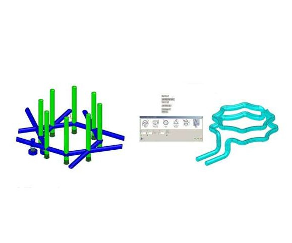
Fig. 1: The conventionally drilled water lines with baffles (left) offer total cooling time of 50.89 seconds. Teardrop-shaped conformal water lines (right; core side shown only) offer total cooling time of 44.97 seconds, a 12 percent reduction in cycle time. Images courtesy 3D Systems - Cimatron Software.
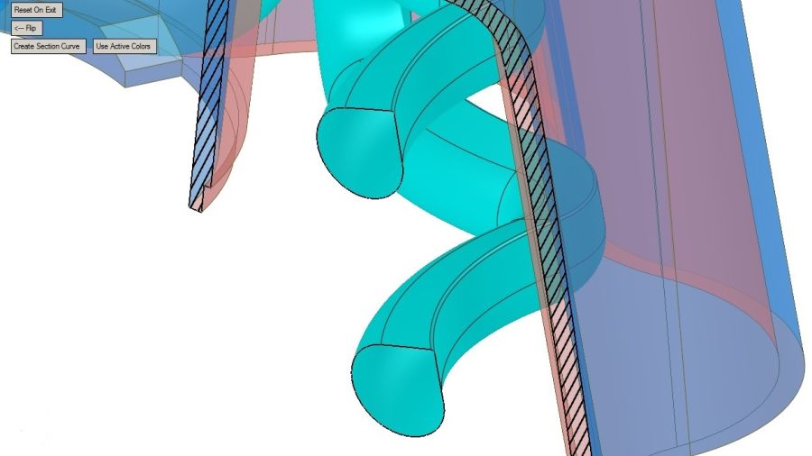
Fig. 2: For teardrop-shaped water lines, it is important to keep the cross-sectional area consistent. The teardrop shape shown here has a cross-sectional area that matches the area of a 7/16-inch diameter line, which allows an even volume of water through the circuit.
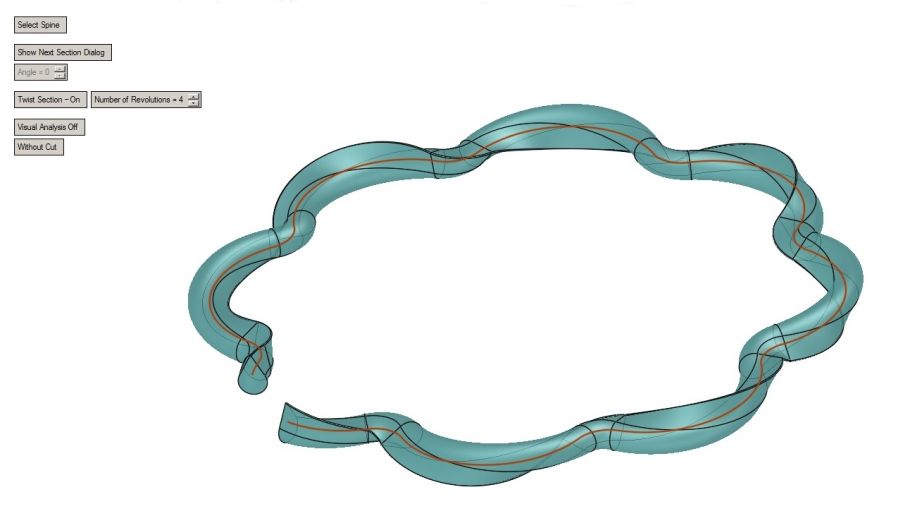
Fig. 3: This water line design has four rotations added to the top circuit that is useful for star, teardrop and plus sign shapes.


This article originally appeared in MoldMaking Technology magazine.
Conformal cooling for plastic injection molds is a hot topic these days, as it can reduce cooling cycle time by as much as 30 percent, providing significant cost savings. Some moldmakers now say that as much as 40 percent of their business involves conformal-cooled mold components.


With advances in additive manufacturing, conformal-cooled mold cores are now often printed and finished in a more cost-effective manner than conventionally machined cores. These cores have a lifespan comparable to conventionally machined cores, but can be replaced in a matter of days instead of weeks.
So, what does it take to design a good conformal cooling water line that will deliver the shortest cooling time while maintaining part quality? Keeping in mind the basic principles of heat transfer is a good starting point:
Water line diameter. The diameter most commonly specified for drilled water lines is 7/16 inch. Any larger can make it hard to get the water line close to the mold surface while avoiding mold components, and any smaller could cause the drill to wander. While additive manufacturing allows us to sidestep the limitations of drilling, using a tried-and-true water line diameter is a safe bet for conformal cooling, minimizing the uncertainties associated with such an approach.
Cross-sectional area. If every water line is drilled with a 7/16-inch drill, the cross-sectional area of the drill diameter remains constant. Although conformal water lines can be made of different shapes, keeping the cross-sectional area consistent is an important principle that should be maintained regardless of the shape. This ensures a constant volume of water flowing through the water line.
Distance to mold surface. Though not a hard-and-fast rule, some shops keep the water line a distance of one diameter away from mold surfaces, while other shops may prefer a two-diameter distance. For most conformal lines, this distance would be dictated by the part geometry. At the same time, it is important that all effort be made to keep the distance a constant. This will help maintain an even heat distribution throughout the part and reduce part warpage.
Water line length. In a conventionally drilled line, water lines should be as short as possible, as drills tend to wander and break if the chips are not evacuated well. Even though it is easy to design long conformal water lines, there are good reasons to keep these lines short: The quicker the water gets in and out across the entire part, the more uniform the heat distribution.
Cross-sectional area, yet again. Since multiple short lines can hit more spots at once and carry heat away more uniformly, some conformal cooling lines are designed as capillaries, that is, a large water line that breaks into multiple smaller water lines that go short distances and quickly enter another larger line that evacuates the water. The general guideline here is that the sum of the cross-sectional areas should equal the cross-sectional areas of the inlet and outlets. This ensures an even flow of the water, further reducing the risk of warpage.
Conformal vs. Conventional
Figure 1 shows two water line designs side by side. On the left is a conventionally drilled water line with baffles, and on the right is a conformal water line (core side shown only). (For the sake of reference, the part is almost 8 inches across and 2.5 inches deep.) The total cooling time with the conventional waterline is 50.89 seconds, while the cooling time with conformal cooling is 44.97 seconds. This is a 12 percent reduction in cycle time.
Figure 2 shows a teardrop shape in which the wall is at an angle that matches the draft of the part. The inlet and outlet lines are standard 7/16-inch diameter, so a typical ¼-inch NPT connector can be used. As discussed earlier, it is important to keep the cross-sectional area consistent, therefore the teardrop shape has a cross-sectional area that matches the area of a 7/16-inch diameter line. This ensures an even volume of water is running through the circuit.
You can also avoid any sharp corners, which is a big help in printing the core. In addition, the shape of the water line makes a very small top radius, which also lends itself to better printing results.
While maintaining a consistent cross-sectional area, the teardrop shape in this example has a longer cross-section perimeter, providing more surface area for the water line to draw heat away from the mold. A 7/16-inch round line has a perimeter of 1.374 inches, whereas a teardrop line with the same area has a perimeter of 1.574 inches.
Keeping water lines short is important for maintaining even heat distribution and preventing part warpage. While the conventional line is more than 75 inches long, the conformal line, with all its curving and turning, has a linear distance of just more than 38 inches. This means the conformal water line is just about half the length, yet it results in 12 percent shorter cooling cycle time than the conventional line.
It is clear that water volume is a major factor for decreasing cooling cycle time. The greater the volume, the better. Another factor is water turbulence. While 3D printing the core will in and of itself generate some turbulence due to the unpolished inside surface of the water line, even more turbulence can be created by twisting the water line. For example, Figure 3 shows the same conformal water line as in the right side of Figure 1, but four rotations have been added to the top circuit.
While such twisting is useless with round water lines, it can be useful for shapes such as stars, teardrops and plus signs. A more intricate shape can create a larger perimeter, so more surface area is available to draw away heat, and the addition of a twist can add even more turbulence.
You should avoid the creation of a wide flat surface across the top of the water line, however. Big, flat tops can be problematic for 3D printing (although some newer printers are better at handling these flat tops).
While these guidelines are not intended to cover everything needed for successful conformal cooling, they can serve as a good starting point. Although conformal cooling might be new to many of us, it still requires a sound understanding of moldmaking fundamentals. In fact, the very same principles that guide us in creating good conventional water lines provide the foundation to the design of an efficient and effective conformal cooling line.
About the Author
David Lindeman
David Lindeman is an application engineer for 3D Systems - Cimatron Software.


Related Content

The World’s Tallest Freestanding 3D Printed Structure
Dimensional Innovations paired additive and subtractive manufacturing to create a monument for the NFL’s Las Vegas Raiders new stadium. The “never been done before” project resulted in the world’s tallest freestanding 3D printed structure.
Read More
3D Printed Cutting Tool for Large Transmission Part: The Cool Parts Show Bonus
A boring tool that was once 30 kg challenged the performance of the machining center using it. The replacement tool is 11.5 kg, and more efficient as well, thanks to generative design.
Read More
Implicit Modeling for Additive Manufacturing
Some software tools now use this modeling strategy as opposed to explicit methods of representing geometry. Here’s how it works, and why it matters for additive manufacturing.
Read More
8 Cool Parts From RAPID+TCT 2022: The Cool Parts Show #46
AM parts for applications from automotive to aircraft to furniture, in materials including ceramic, foam, metal and copper-coated polymer.
Read MoreRead Next

Video: Moldmaker Succeeding with Conformal Cooling
B&J Specialty now complements its machining capabilities with metal 3D printing for making mold inserts with cooling channels that follow the contours of the mold. The shop is even revisiting challenging molds from the past.
Read More
Design Enhancements for Conformal-Cooled Insert Leverage 3D Printing Capabilities
A collaborative mold project reveals that the value of 3D printing isn’t in the process, it’s in the products.
Read More
At General Atomics, Do Unmanned Aerial Systems Reveal the Future of Aircraft Manufacturing?
The maker of the Predator and SkyGuardian remote aircraft can implement additive manufacturing more rapidly and widely than the makers of other types of planes. The role of 3D printing in current and future UAS components hints at how far AM can go to save cost and time in aircraft production and design.
Read More