
Verifying Structural Integrity of Metal 3D-Printed Parts
X-ray computed tomography, or micro CT, offers insight into the inside of AM parts.
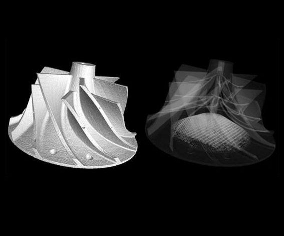
Micro CT scans can reveal external and internal features.
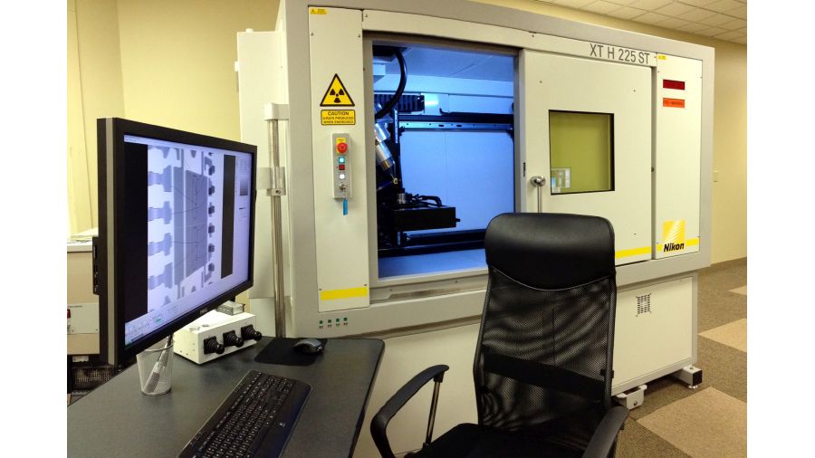
An X-ray computed tomography system from Nikon Metrology.
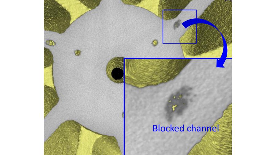
Scans reveal blocked channels without destroying the parts.
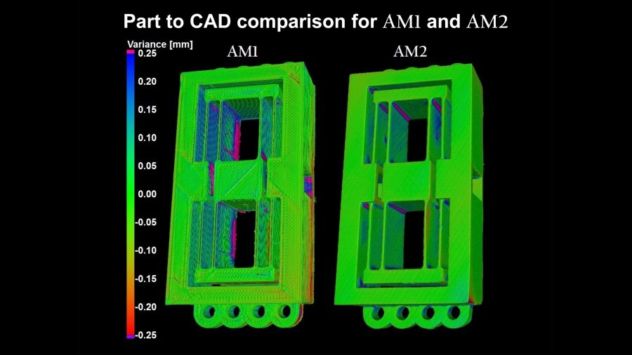
This part-to-CAD comparison shows FDM and STL versions of the same part.
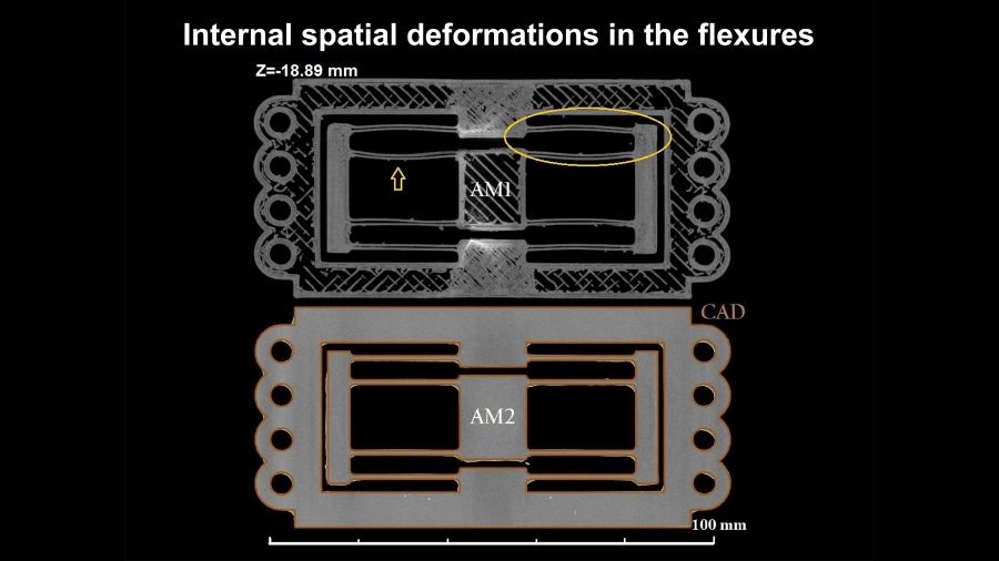
Flexure deformations can be revealed by CT scans.


Metal additive manufacturing is being increasingly considered for lowering component weight without compromising strength, particularly in aerospace applications where decreased weight leads to increased efficiency. For safety-critical aerospace components, however—as well as for similarly critical automotive, energy and medical components—it is essential to know whether voids or inclusions are present in the AM part, how large they are (both individually and in total), and where they occur, as well as whether the dimensions of the part conform to those of the design.
In such cases, X-ray computed tomography (micro CT) is a powerful answer. By supplying a full 3D density map of the samples, micro CT gives all this information in an easy-to-read visual format.


Conventional manufacturing provides an analogy for why this inspection is valuable. Using conventional manufacturing techniques, one would always inspect a weld for voids and inclusions. Consider that, in metal additive manufacturing, the entire sample is essentially one large weld.
And the entire sample needs to be inspected. Because of the nature of the metal 3D-printing process, with partially melted powder flying around in the chamber, the position and nature of defects is random. With more traditional manufacturing processes, a few radiographs at specific orientations can give peace of mind. But with additive manufacturing, micro CT can ensure evaluation of the whole part.
What do we look for when checking the structural integrity of AM parts? Several things:
- Powder residues blocking channels.
- Defects, including porosity, contamination and cracking.
- Departure from the CAD model, such as wall thickness variation or warping.
For example, a mold made using selective laser melting is designed to make a small knocker for a watch mechanism. Micro CT can validate the cooling and flow channels built in by the AM process to an accuracy of 50 to100 microns (depending on acquisition parameters). From flow and cooling simulations, this is known to be of sufficient accuracy for the purpose.
In fact, micro CT can find defects within samples down to a resolution given by the number of pixels across the detector. Given a sample 100 mm across, and a detector 2,000 pixels across, the limiting resolution would be 50 microns. Resolution is also limited by the focal spot size of the X-ray source, which may range from 80 microns for high energies down to less than 1 micron for low energies.
Defects below the nominal resolution may also be spotted if the contrast with the surrounding material is great enough. For example, given a 3-micron X-ray focal spot, we can still see a 0.5-micron gold foil edge-on.
The size of sample which can be scanned with CT depends on the material it is made of and the energy of the X-ray source, measured in kilovolts (kV). Larger lower-density samples can be scanned, as can smaller higher-density samples.
Typical largest samples are:
- 225 kV – aluminum piston heads; diesel injectors
- 450 kV – aluminum cylinder heads; aircraft turbine blades
Maximum part size also tends to be limited by the size of the detector, as well as by the penetrating power of the X-rays. This decreases as material density and atomic number of the material increases. Much more plastic can be penetrated than steel, and much more steel than lead.
To illustrate micro CT’s applications to AM, here is an example taken from a paper presented at the American Society for Precision Engineering. A flexure mechanism fabricated by additive manufacturing is investigated by X-ray CT scanning methods. A first flexure sample (AM1) was manufactured by fused deposition modeling (FDM). A second sample (AM2) was manufactured by stereolithography (STL). For reference, the FDM and STL processes have printing resolution of approximately 100 microns and 0.5 micron, respectively.
Micro CT scans show variance analysis for both AM1 and AM2 flexures against the original CAD model. From the measurements, it can be seen that deviations from the nominal geometry (CAD model) rise up to ±0.25 mm and larger when using the AM1 process. In contrast, the AM2 process generated part-to-CAD deviations mostly in the range of ±0.1 mm, with exceptions around surface edges and corners.
In addition, a cross-section of AM1 shows residual internal and spatial deformations. On the other hand, the manufactured part generated by the AM2 process (see the fifth illustration in the slideshow above) does not reveal the presence of major deformations in the thin-walled flexure leaf structures.
Modern micro CT is fast enough to be suitable for production-line use. Moreover, CT scanning of similar parts can be automated for loading and unloading. Scan times down to a few tens of seconds per part are possible. Users gain:
- Insight into the inside of AM parts.
- Faster optimization of the AM process for a new part.
- Quality control—higher confidence in part consistency.
- Cost savings by avoiding destructive testing.
3D printing rewrites many manufacturing rules, but it demands a different approach to inspection. X-ray computed tomography is a powerful partner for nondestructively assuring geometrical and tolerance quality control of AM parts.


Related Content

Inspection Method to Increase Confidence in Laser Powder Bed Fusion
Researchers developed a machine learning framework for identifying flaws in 3D printed products using sensor data gathered simultaneously with production, saving time and money while maintaining comparable accuracy to traditional post-inspection. The approach, developed in partnership with aerospace and defense company RTX, utilizes a machine learning algorithm trained on CT scans to identify flaws in printed products.
Read More
Dimensionics Density Offers Automated Density Determination for AM-Produced Parts
Formnext 2023: Dimensionics Density’s automatic density determination technology provides automated, accurate and repeatable density determinations for additive manufacturing production.
Read More
Zeiss Hosts Digital Event for Metrology and Software April 15-19
The event is designed to offer a unique opportunity to gain new, interesting insights and exchange ideas with industry experts from all over the world.
Read More
Making Sense of Data from Directed Energy Deposition (DED)
“It should be easier to qualify an additive part than a casting,” says Formalloy CEO Melanie Lang. The company’s tools for capturing and analyzing data are bringing this vision closer to reality.
Read MoreRead Next

Can Topography Scans Redraw the Metal Additive Inspection Map?
A new topographical mapping technology aims to detect, record and display flawed metal melt regions as they’re created.
Read More
Validating and Qualifying
X-ray technology can validate the internal geometry of additively-manufactured parts in 3D without destroying the part.
Read More
3D Printing Brings Sustainability, Accessibility to Glass Manufacturing
Australian startup Maple Glass Printing has developed a process for extruding glass into artwork, lab implements and architectural elements. Along the way, the company has also found more efficient ways of recycling this material.
Read More