


The component was cut open to reveal the feature that was never part of the model. As it happens, the cause was not CAD-related, though many guesses on social media went there.
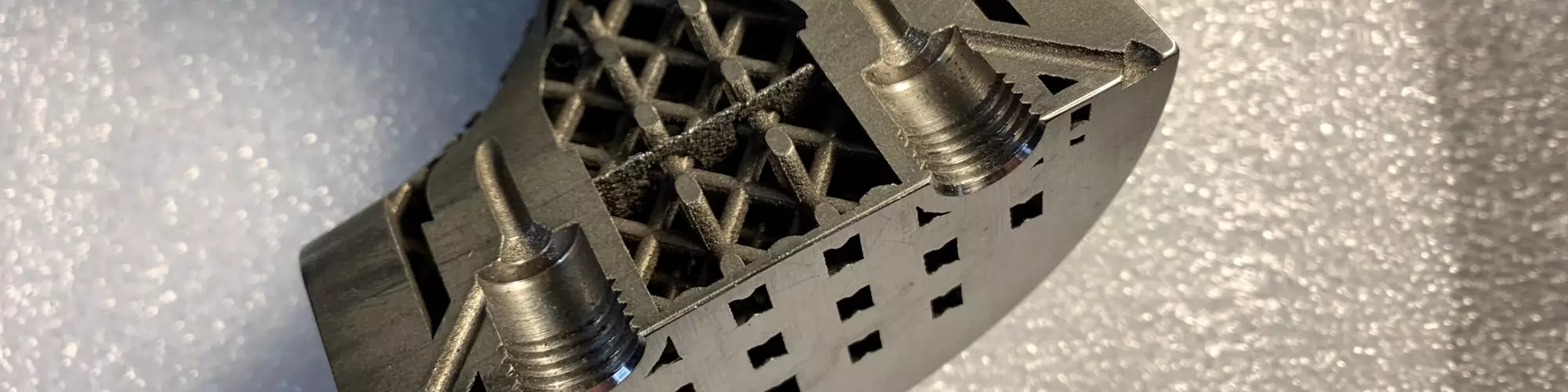
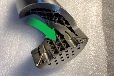
On the latest episode of our video series, “AM: Why the Failure?”, Penn State professor of additive manufacturing Tim Simpson and I discuss a stainless steel component related to oil and gas extraction that was made through laser powder bed fusion. For weight reduction, the component’s inner volume consists of a lattice structure. However, the build produced a barrier through the lattice and through the part that appears nowhere in the original CAD model. This barrier might have resulted in complete failure by cutting off the passages necessary for fluid flow, but fortunately, the feature appeared near enough to one end of the part that a drill could still reach it and open it up.
What happened here? As Tim and I discuss, the cause of this error relates to a power failure and subsequent restart of the build. He makes the case for an uninterruptible power supply, an investment that may pay for itself after saving just a few additive builds. However, most of those who made guesses in social media instead suspected a problem in CAD modeling, likely related the use of the STL geometry format. STL is a common file format for additive manufacturing — it has its challenges and it even produced a different, unrelated challenge in producing this part, so Tim and I also get into a discussion of STL and its alternatives. | This episode of AM: Why the Failure? brought to you by Verisurf
To see a preview and offer a guess about our next AM build failure before we film the episode, follow the #AMWTF hashtag on LinkedIn.
Related resources:
- LinkedIn post about this part, with many guesses
- Surface defects resulting from STL modeling
- Case study: uninterruptible power supply
Transcript:
Pete Zelinski, Additive Manufacturing 00:00
Why The Failure is sponsored by Verisurf Inspection and Measurement Software. Stick around after the episode to learn more.
Pete Zelinski 00:12
Hello, welcome to our series that asks, “Why the failure?” This is our second episode in this video series. Real simple what we're doing here — we share additive manufacturing fails on social media, ask for guesses and then we reveal what really happened. I'm Pete Zelinski, AdditiveManufacturing.media. Let me introduce my partner in failure. Here's Tim Simpson, professor of Additive Manufacturing at Penn State University. Hi, Tim.
Tim Simpson, Penn State University 00:41
Hey, Pete, how are you doing?
Pete Zelinski 00:43
To show the failure this time, I'm going to have to dismantle this part — the failure is on the inside. Before I do that, what is this thing? It's got good heft. Tell us about this part and the system it was 3D printed on.
Tim Simpson 01:00
Sure. Yeah, you should feel that thing before the lattice was in there, talk about a big paperweight. So that's actually an oil and gas component. It goes downhole — you stack many, many, many of those up together — and the internal channels in there, as you spin it, centrifugal force is either pumping fluid up or pumping fluid down, depending on which way it's spinning. The goal there was to say, “Hey, as a possibility, could we look at additive for lightweighting this component? Because we need the outside, we need the internal channels, but sort of the rest of that space, do with it what you want.”
Pete Zelinski 01:40
Okay, so we got a lot of responses to this one, comments on the defect we found. It's on the inside, I’ve got to open this up to find it. You cut the part, you sliced it apart in this way so we could see the failure. Here it is, right here. It is this feature that was never supposed to be there — not part of the CAD model in any way. As I said, we got a lot of guesses on social media as far as what went wrong here, and why this extra feature occurred on the inside of the part, within these lattices. A lot of the guesses were software related, weren't they?
Tim Simpson 02:24
Yeah, everybody seemed to pile on STL all of a sudden. This was made on a laser powder bed fusion system: powder particles, thin layers and a laser coming down. Typically, you would take your CAD model and export it as an STL. We then bring it in, using [Materialise] Magics to orient it into our build prep and then print it on an EOS M 270. A lot of people thought, somewhere in that conversion — particularly going from CAD to STL, or when you bring STL in and do an automatic repair or a check of it — that if one of the vertices was off, then it would realign it or do those sorts of things if the triangles didn't align.
Matthew Duffey, Action Mold and Machining, thought perhaps one of the triangles was open, and then when it automatically got fixed, it stretched it out and, all of a sudden, you have a plane inside the structure. Bob Markley, 3rd Dimension, said he'd been caught on this once or twice. You know, you wouldn't catch it — think about it — if this was only on one or two layers, right? That whole part is five inches tall, we're at a very thin layer, right? You'd have to scroll through all those slices to see if you picked it up.
Pete Zelinski 03:43
Bob Markley also — sort of tongue-in-cheek — posted another theory within the social media response. Can you read that? Because I think we're gonna circle back to that one.
Tim Simpson 03:55
Yeah, I love this. His theory number two was, and I quote, "This is so obvious, flying squirrels got into the machine and nested in the galvos, causing them to move slow. Always blame the squirrels, they are nuts." Even had a little squirrel emoji there with it as well.
Pete Zelinski 04:12
All right, put a pin in that. The STL/software answer, while very credible, was not the explanation, was it? Who were some of our respondents who landed closer to the truth?
Tim Simpson 04:28
Again, it's one of those things that it's sort of easy to pull on that thread, right, and go that route. But Sabrina Marques, one of our repeat responders, from SEAM Research Centers — she went through and started as well with the software, "Hey, maybe it's an STL issue when you're then repairing the triangles." Then her third response here said, "Actually, due to the line marks in that solid region, perhaps it was an interruption to the process. Maybe it stopped for some reason, maybe the powder was out, maybe electricity ran out. And maybe then the process had to be restarted, instead of starting where it had stopped. Maybe it started at the lower level, and then, eventually, the operator caught it and fixed it.”
Similarly, Matthew Shomper from Tangible Solutions went out on a limb, I think he was among the first to really say, "Hey, maybe it's not a modeling issue, right? Sometimes the software catches it, fixes it and slices it.” But looking at it, I think he was the first to say that the operator, during a restart, basically, looking at the lower layers versus where that restart was — perhaps the machine stopped and then when it restarted, it went back to layer zero instead of at that particular z-height.
Pete Zelinski 05:48
So, Tim, as we're sort of hinting at here, these latter responses, they got it kind of right. Give us the concise story. What really happened here, how did we get this failure?
Tim Simpson 06:00
It was not a software modeling issue. We have had that occur in others, but that was not the case here. As Sabrina, Matthew, Pierre and a couple others responded, it was a power issue. The power actually went out on the machine. And then when the operator restarted it, correct, it was restarted at layer zero. So the software, the build plan reset at zero as well. It started building layer zero there at the z-height, and most of these parts have a radius of curvature that mounts them to the plate to reduce residual stresses. The zero and first layer, too, are a little bit wider than the actual diameter of the part itself. If you saw the whole part before it was machined, you would see that that plane extends outside of the part, and then it becomes a bit more obvious, “Hey, this is not an internal software issue, this is a restart of the different layers there, and you can see it's a couple layers thick.” The operator did come back and took a look, made sure things were running, noticed something was off and restarted it at the appropriate layer to finish building that part.
Pete Zelinski 07:19
So there was a temporary wrong restart that got caught quickly, but there was a wrong restart at layer zero. That's basically what we're seeing here, the false layer zero. Did that cause the part to become dysfunctional?
Tim Simpson 07:37
The part, the internal channels that go through are very critical. If those are blocked for any reason, then you can't get the flow and the part is not going to function. So we were very worried, depending on the height of where that plane went through, did it cut off those internal passageways, or were we able to get through there? And so that's why we cut it at the end. The other big concern on this is if you are stopping in an intermediate layer and then restarting, does that now become a weak point in your structure? Because it can cool off, you restart, different microstructure that builds up there in heat treatment. We got lucky in this regard, in that it didn't damage the structural integrity and didn't damage the functionality — the internal passageways there remained open, luckily, despite the error that occurred.
Pete Zelinski 08:28
Part of the internal passages that were needed, we see them here, and this fail happened early enough that a drill could still reach through and open up where you needed to open up. This is an example of an effect of a power interruption and an illustration of the hazard and difficulty that interrupted power can bring to a laser powder bed fusion process. You're in a better state now with regard to reliable power, and part of why you got that way relates to a squirrel, right? Can you tell that story?
Tim Simpson 09:10
Well, first and foremost, if you don't have an uninterrupted power supply on some of your systems, regardless of the stability of your electrical grid, it's probably well worth the investment. You know, they may cost $20,000, $30,000, $40,000 depending on what you get, but one or two failed builds at $20,000 each will immediately pay for that, right? So it pays for itself. But to your point, Bob was not far off the mark there. We had earlier that year, it wasn't that build, but eventually a squirrel did eat into the wires, blew the transformer that was already a bit shaky there — that is what had led to some of the disruptions in that particular build — but eventually a squirrel took it out, and we got a new transformer in and power has been running steady ever since. And then we've got the backup there if we need it. So, funny what nature can do to you sometimes.
Pete Zelinski 10:05
I want to pause and draw a circle around that. Bob Markley, you were more correct with the squirrel theory. All that said, a whole lot of our respondents pointed to software and pointed to the problem of using STL as the model format. As it happens, there was a challenge with this part related to STL, and I think we can see that in the photo here. Can you describe what we're looking at?
Tim Simpson 10:35
Absolutely. I think you can see the vertical lines on the outside there. It sort of looks, you know, tessellated. That's because of the STL file conversion. This lattice, and this part — the outer diameter is about three inches, and then you've got small lattices inside that are maybe an eighth of an inch in diameter. And so when you approximate, export this as an STL, the tessellation, sort of the accuracy and tolerances for the small struts versus the larger part, you can't change that. You either have to get it very accurate for the smaller ones, and then your bigger one blows up, or vice versa. These are just some of the inherent limitations in the STL file format.
In this case, we overcame those. We made sure our internal lattices were approximated well. We dealt with the external tessellation by having some machining allowances, that then, once we put it on a lathe and turned it a couple of times, it was nice and smooth and we were good to go. But that remains an issue now, and it certainly frustrates designers and engineers with their CAD models to have to take nice smooth curves and approximations and break them up into a bunch of triangles to then be able to 3D print it. Nobody wants that.
Pete Zelinski 11:58
STL was not the cause of this error, this error was because of power interruption. But STL ultimately is the reason why there's a smooth machined surface here. This part was machined on a lathe to deal with that modeling issue. Okay, Tim, STL is kind of a standard way to deal with modeling related to additive manufacturing. Is it the only option? Are there alternatives?
Tim Simpson 12:22
No, I think that's one of the interesting advances now — trying to avoid having to go to STL altogether. We saw several responses from the team at nTopology, I think, #DeathToSTL. The nice thing within their geometry, they're slicing directly, then exporting it. So, they're skipping that STL conversion altogether. Bob Markley in his response had mentioned 3DXpert [from 3D Systems], with their direct metal printing, as they call it. They go directly from their CAD model, slice it, and are able to print it. So, we're now seeing advances in the software domain that allow us to sort of skip over that intermediate step, given the computing power and tools that are available to us these days.
Pete Zelinski 13:09
All right, thank you, Tim. Keep watching everyone. What you want to do is follow the hashtag #AMWTF in LinkedIn. We're going to share our next build fail there, we're going to ask for your guesses and then, Tim, you'll join me again to talk about what really happened.
Tim Simpson 13:26
Absolutely. I know we've been picking on powder bed fusion a lot lately, so we'll switch over and talk about some failures with directed energy deposition next time around, so don't miss it.
Pete Zelinski 13:36
Oh, awesome. Okay, so DED gets its due coming soon.
Pete Zelinski 13:41
Thank you to our sponsor, Verisurf, a measurement solutions company. Use Verisurf software as a common measurement platform across the enterprise for analysis of parts made through additive manufacturing and other operations. Capabilities include quality and inspection reporting, advanced surface analysis and reverse engineering. Built on powerful CAD/CAM, Verisurf employs digital model based definition, open standards, universal compatibility with CMMs and comparison of measurement data to nominal 3D CAD or STL files. Regardless of operation — 3D printing, machining, casting or molding — Verisurf supports the process by verifying the part. Maintain the digital thread through design, engineering, manufacturing and part validation. Learn more at Verisurf.com.
Read Next

Video: The STL File Can Produce Surface Defects in 3D-Printed Parts
Timothy Simpson of Penn State University discusses the influence of model definition in additive manufacturing and what to do about its effects.
Read More
Metal 3D Printed Part Should Be Flat, Has Bubble — AM: Why the Failure? #1
What should have been a straightforward application of laser powder bed fusion to make a simple component in 316L stainless steel turned into a printing fail. See why the failure happened.
Read More
Calling for Backup: Power Protection
An additive manufacturing service provider solved quality issues with an uninterrupted power supply, enabling more reliable production.
Read More