
Meeting the Machining Challenges of Additive Manufacturing
You can 3D print the part, but can you finish it? Here is how to overcome the challenge of part deflection in the machining of lightweight, complex AM parts.
The geometric complexity of a 3D-printed part might mean special workholding is necessary for machining it—perhaps workholding that is 3D-printed as well.
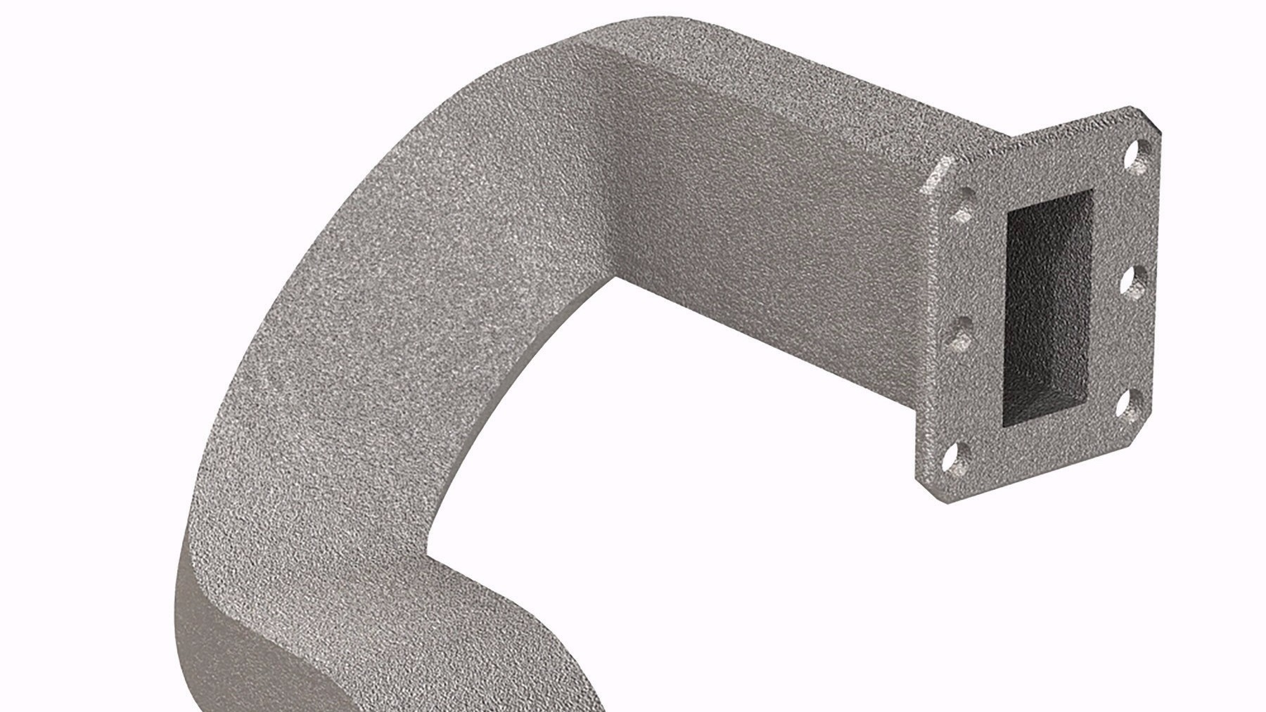
Fig. 1. This satellite microwave guide produced through selective laser melting is an example of an AM part that presents challenges during machining.
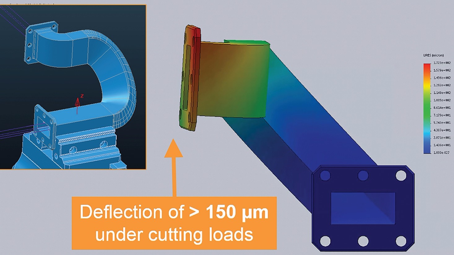
Fig. 2a. FEA reveals that the part could be redesigned to better withstand cutting forces.
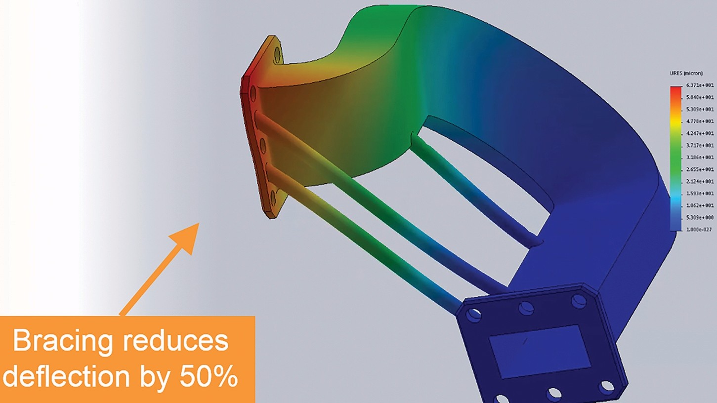
Fig. 2b. However, this adds to the mass and footprint of the part, cancelling out some of the reason to use AM in the first place.
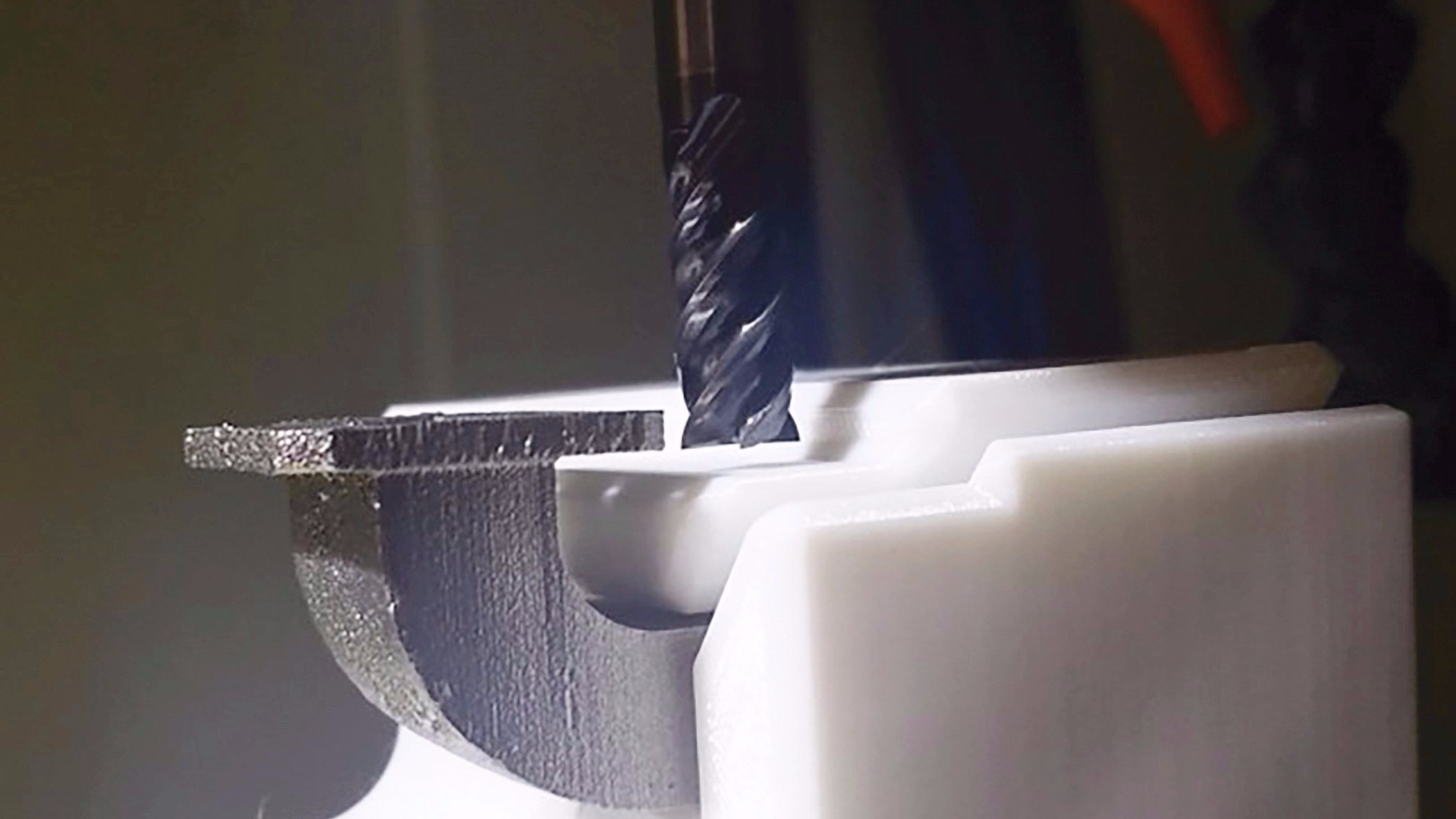
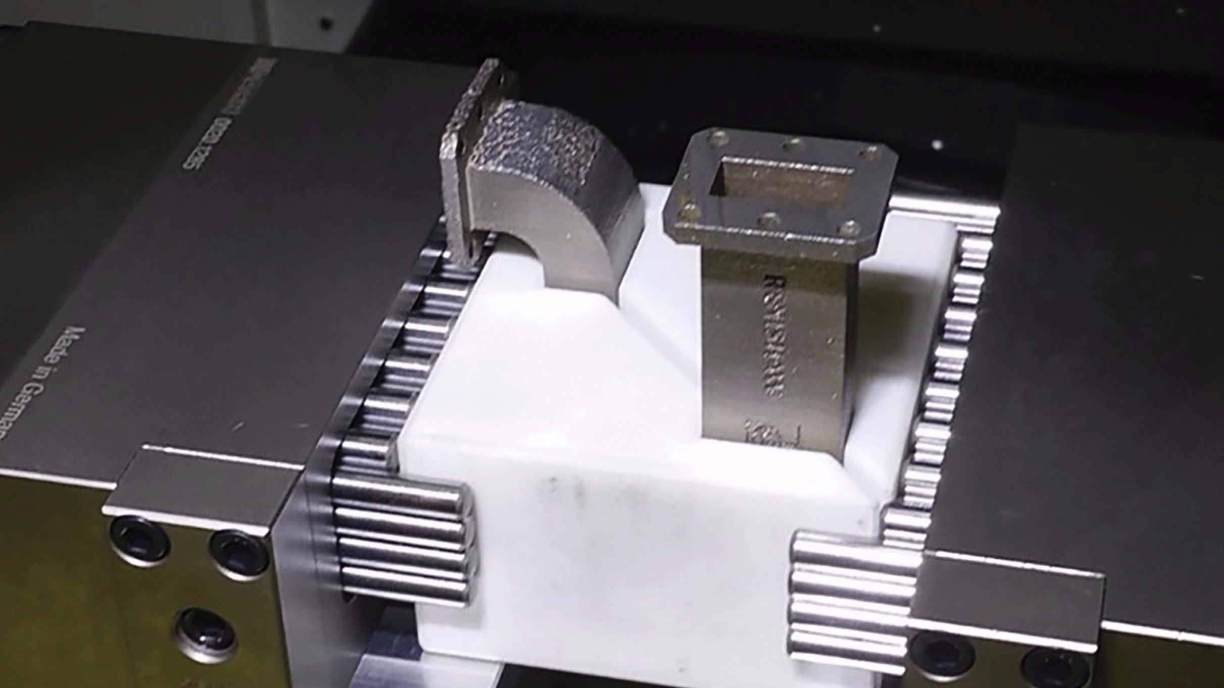
Fig. 3. 3D-printed jaws matching the form of the part allow the part to be encapsulated within the workholding. Advancing from the example at the start of this article, here are custom jaws that contain and secure even more of the component.
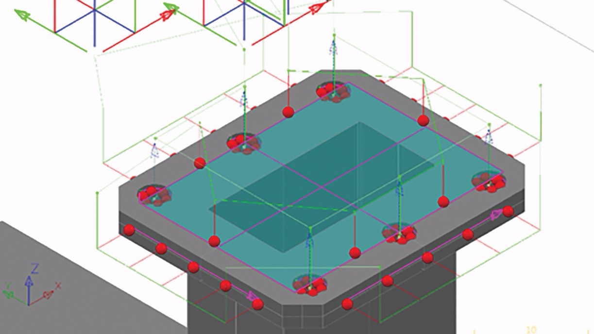
Fig. 4. Software uses probing points to find a “best fit” for the end flange of the wave guide. An initial alignment using the top face of the flange and points around its edges is followed by probing the six holes.
Share
Read Next


Producing functional parts via additive manufacturing (AM) enables us to design and manufacture products that we just can’t make any other way. With the flexibility of 3D printing, we can realize part-performance benefits such as lightweighting and thermal efficiency, we can integrate separate components into consolidated designs with complex forms, and we can do all this within a build process that is often highly automated and highly efficient it its use of materials, producing little waste.
AM has a dark side, however. The benefits above are offset against some very real and potentially painful challenges with postprocessing. Finish machining of AM parts can be challenging directly because of their light weight and their complex forms. Both attributes can lead to problems with workholding and vibration and can result in poor process yields. Furthermore, there is the additional problem of aligning complex components when they lack precise geometric datums in the as-built state.


This article will look at the challenge of making lightweight parts stiff enough for effective finish machining. We will explore how to realize effective workholding solutions to make non-rigid additive parts machinable. We will also demonstrate how machine tool probing can be used to perform sophisticated alignments of AM parts, enabling us to “find the good part” within the shape that we have built and produce the critical datum surfaces correctly.
The Need for Machining
As versatile as it is, an additive or 3D-printing-style process, particularly in metal, cannot produce features with very fine tolerances. Post-process machining is often needed to produce precise round holes and smooth, flat surfaces for interfacing with other parts. Yet lightweighting often has the effect of reducing the stiffness of AM parts, which can mean that they do not stand up well to the machining process. The complex forms of AM parts also make them hard to grip securely without causing damage. And finally, it is common to produce the datum features on additive parts after the build itself, so setting up components for finishing can be tricky.
There are a lot of similarities here to the challenges that manufacturers of composite and super-plastically formed parts face—namely, complex shapes that may have some distortion onto which precision features must be machined. Users of AM can learn from the best practices in these other sectors while adding an AM twist of their own.
Case Study: Microwave Guide
Among the machining challenges characteristic of AM, the first consideration is whether the part is likely to be stiff enough to cope with the loads it must bear during machining. Many questions arise from this. Will the part deflect away from the cutter, and will it vibrate such that we get tool chatter and poor finish on machined surfaces? If yes, what can we do about it? Can we design the part differently to make it stiffer? Or if that is not an option, how can we hold the part to support it sufficiently that it will not deflect or vibrate excessively? We will use a case study to explore these questions.
Another important challenge, supposing that we now have a part that is designed or supported in a way that provides sufficient rigidity, is how to datum and align it on our machine tool. The complex form of AM parts, the fact that there may be some distortion in the build process and the lack of crisp datums all mean that we have to somehow “find the good part” inside the shape that we have made. Getting an optimal five-axis alignment of our AM part is critical.
The case study part we will look at is a microwave guide designed for a telecom satellite application (Figure 1). The critical performance factors of the part are its weight, the efficiency with which microwaves are transmitted through it and the space claim that it makes on the
satellite payload.
Step 1: Effect of Cutting Forces
First, we need to know if our part is going to be rigid enough to handle the cutting forces that we will apply to it. This could be determined by running experiments to assess these forces using a scrap build plate of the appropriate material attached to a dynamometer. The peak and typical cutting forces found this way then would be applied to our part using finite element analysis (FEA). The effect of cutting forces could also be observed through trial cuts on the actual part.
When we machine the wave guide, we encounter problems. The part deflects away from the tool during cutting and also springs back, leading to resonant vibration, tool chatter and gouging of the component surface. The result is that the periphery of the flange is undersized and the surface finish is poor.
We need to improve the stiffness of the part during cutting. There are two possibilities: change the part design or change the way we support it during machining. Let’s address part design first.
Step 2: Improvement by Design?
One approach is to consider whether we can make some design changes to our AM part to make it stiffer. In the FEA image (Figure 2), we have added some braces to connect the two ends of the component and reduce the deflections that we see during cutting.
The problem with this approach is that we have increased the footprint of the part, impinging on space that could be occupied by other components and making the design less efficient overall. Plus, the extra stiffness that we achieve may still not be sufficient to make machining of the part viable using just a basic workholding method. This leads to Step 3.
Step 3: Rethinking Workholding
If we cannot easily change the part design without losing some of the benefits that AM has provided us, then we should look at other ways to hold the component during metalcutting. We need to find a way to distribute support across the component to minimize deflection and vibration without causing damage to the part as we clamp it against a hard fixture. A range of methods are available, including adhesive workholding and workholding that conforms to complex forms using an array of moving pins.
But we can also consider an additive alternative in which we create some encapsulating 3D-printed jaws (Figure 3). These distribute the clamping force across the metal part, reducing the risk of part distortion and surface damage. They also support the metal part closer to the machined features, reducing deflection and vibration.
Step 4: Getting Ready to Machine
Now that we have our part fixtured firmly and securely, we are ready to start cutting metal. Or are we?
One of the major causes of machining scrap is poor machine tool geometric performance, in both absolute terms and relative drift over time. Errors arise when the linear and rotary movement of the machine’s axes fall outside the tolerances necessary to manufacture an accurate part. This becomes critical when we need to hold geometric tolerances between datum features that are machined in different orientations, as is the case with our wave guide.
We can use metrology on our machine to characterize its geometric accuracy, employing a touch probe to check the linear and rotary movements. NC-Checker by Metrology Software Products is one software tool that can be used to analyze these checks. It combines the probing results in one report, allowing us to confirm how accurate our five-axis machine tool actually is. A benchmark of our machine tool, taken before we start machining, gives us a reference point to help identify machine issues that could affect performance. Over time, this report can also show machine drift and alert us when the machine reaches a critical point at which maintenance may be required.
Then, if everything is OK with our machine tool, we can start cutting, right? Not quite.
AM turns many aspects of manufacturing on their heads, and one example of this is the way in which datums are generated. In conventional machining, we tend to create our datums first, and then use these features to align and position the part for subsequent machining operations. We cannot do this with AM, as precision datums have to be added in a final machining operation after all the other surfaces have been generated.
The challenge with setting AM parts is therefore taking into account the actual shape that has been built so that we can finish the part successfully. Essentially, this involves understanding the condition of the part in all the regions where we plan to cut precision features, taking into account planned stock allowance as well as unplanned part distortion. We are seeking an alignment of the part that leaves enough material in all of these locations to allow consistent and effective cutting.
Once again, we can use probing to achieve this. A useful tool here is NC-PerfectPart (also from Metrology Software Products), which provides a range of multi-point alignment options to take account of the actual material condition to find a “best fit” setup for finish machining. For the wave guide, the initial alignment process is iterative, using the condition of the material at all of the measured points to find a multi-axis alignment and position offset that allows for the most consistent cutting conditions. The second stage of the setting process then involves probing the six holes in the end flange to find the optimal position offset to enable cutting of the hole pattern with the most consistent cutting conditions (Figure 4).
Step 5: Machining
At last! With the part optimally fixtured and aligned on our five-axis machining center, we are ready to cut the datum features. The resulting component has critical dimensions that are within tolerance and shows good surface finish. Tool chatter and wear are much reduced compared to our earlier machining trial.
Summary
Precision machining is often the “finishing touch” in an additive manufacturing process chain. It is a high-stakes process—if we get it wrong, we might scrap a valuable component. It is also challenging because functionally optimized, lightweight AM parts may not be very rigid and often need supportive workholding during finish machining. Their complex shapes can require equally complex fixtures, and 3D-printed encapsulating jaws can provide a good solution.
Metrology is essential when machining to tight tolerances, particularly when part distortion is a concern and when geometric tolerances must be met. Probing allows for complex alignments to “find the good part” inside, accommodating part distortion and making finish cutting conditions more consistent.
About the Author

Marc Saunders
Marc Saunders is director of Global Solutions Centers for Renishaw, provider of both metrology technology and technology for metal AM. He would like to thank his colleagues Mark Kirby and Mark Buckingham for their contributions to this article.


Related Content

VulcanForms Is Forging a New Model for Large-Scale Production (and It's More Than 3D Printing)
The MIT spinout leverages proprietary high-power laser powder bed fusion alongside machining in the context of digitized, cost-effective and “maniacally focused” production.
Read More
New Zeda Additive Manufacturing Factory in Ohio Will Serve Medical, Military and Aerospace Production
Site providing laser powder bed fusion as well as machining and other postprocessing will open in late 2023, and will employ over 100. Chief technology officer Greg Morris sees economic and personnel advantages of serving different markets from a single AM facility.
Read More
Zeda AM Production Plant in Ohio Now Open — Thoughts on the New Facility
73,000-square-foot metal powder bed fusion plant includes extensive machining capability plus separate operational models for serving medical versus other businesses.
Read More
The World’s Tallest Freestanding 3D Printed Structure
Dimensional Innovations paired additive and subtractive manufacturing to create a monument for the NFL’s Las Vegas Raiders new stadium. The “never been done before” project resulted in the world’s tallest freestanding 3D printed structure.
Read MoreRead Next

At General Atomics, Do Unmanned Aerial Systems Reveal the Future of Aircraft Manufacturing?
The maker of the Predator and SkyGuardian remote aircraft can implement additive manufacturing more rapidly and widely than the makers of other types of planes. The role of 3D printing in current and future UAS components hints at how far AM can go to save cost and time in aircraft production and design.
Read More
4 Ways the Education and Training Challenge Is Different for Additive Manufacturing
The advance of additive manufacturing means we need more professionals educated in AM technology.
Read More
Hybrid Additive Manufacturing Machine Tools Continue to Make Gains (Includes Video)
The hybrid machine tool is an idea that continues to advance. Two important developments of recent years expand the possibilities for this platform.
Read More