
Large-Format Additive Manufacturing: Viable for Autoclave Tooling?
SABIC and the University of Dayton Research Institute explore the potential of using large-format additive manufacturing (LFAM) technology for creating autoclave tooling used in manufacturing aerospace composite parts.
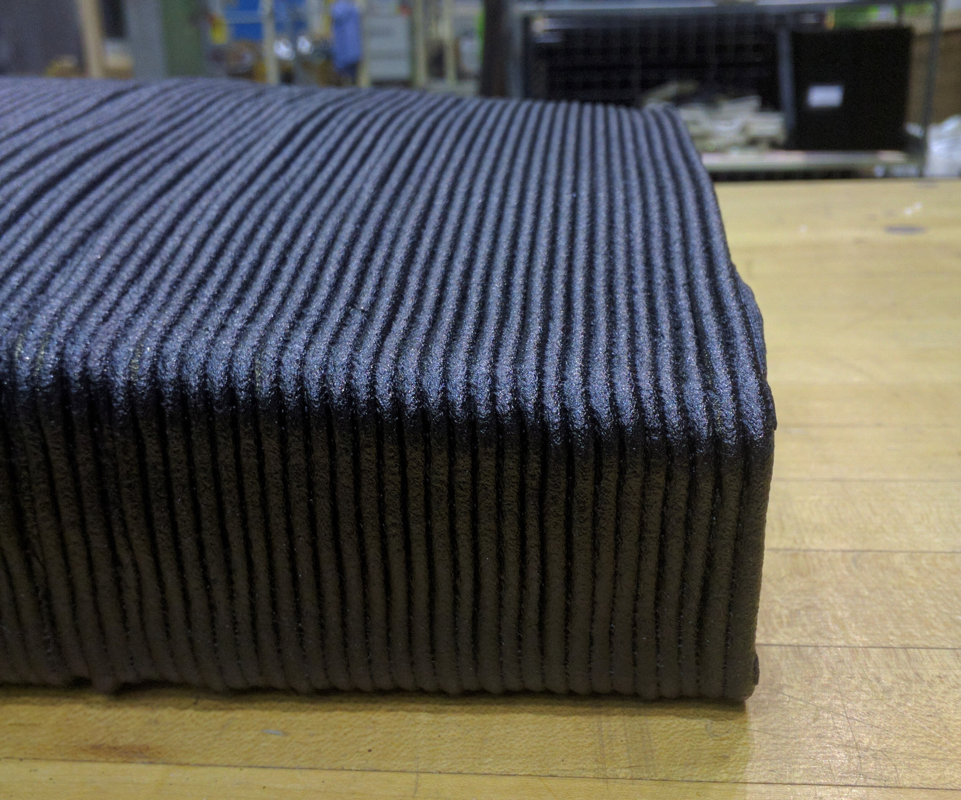
Figure 1. Tool as printed using Thermocomp AM EZ006EXAR1 compound. Image credits: SABIC
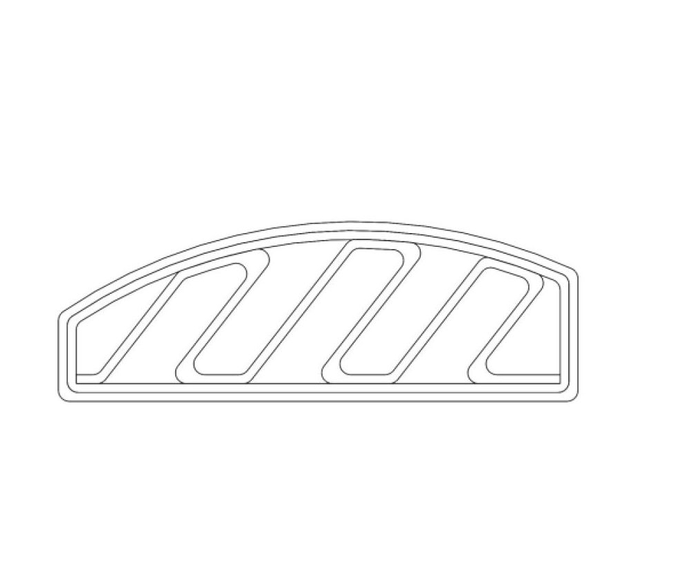
Figure 2. Diagram of internal rib structure of tool.
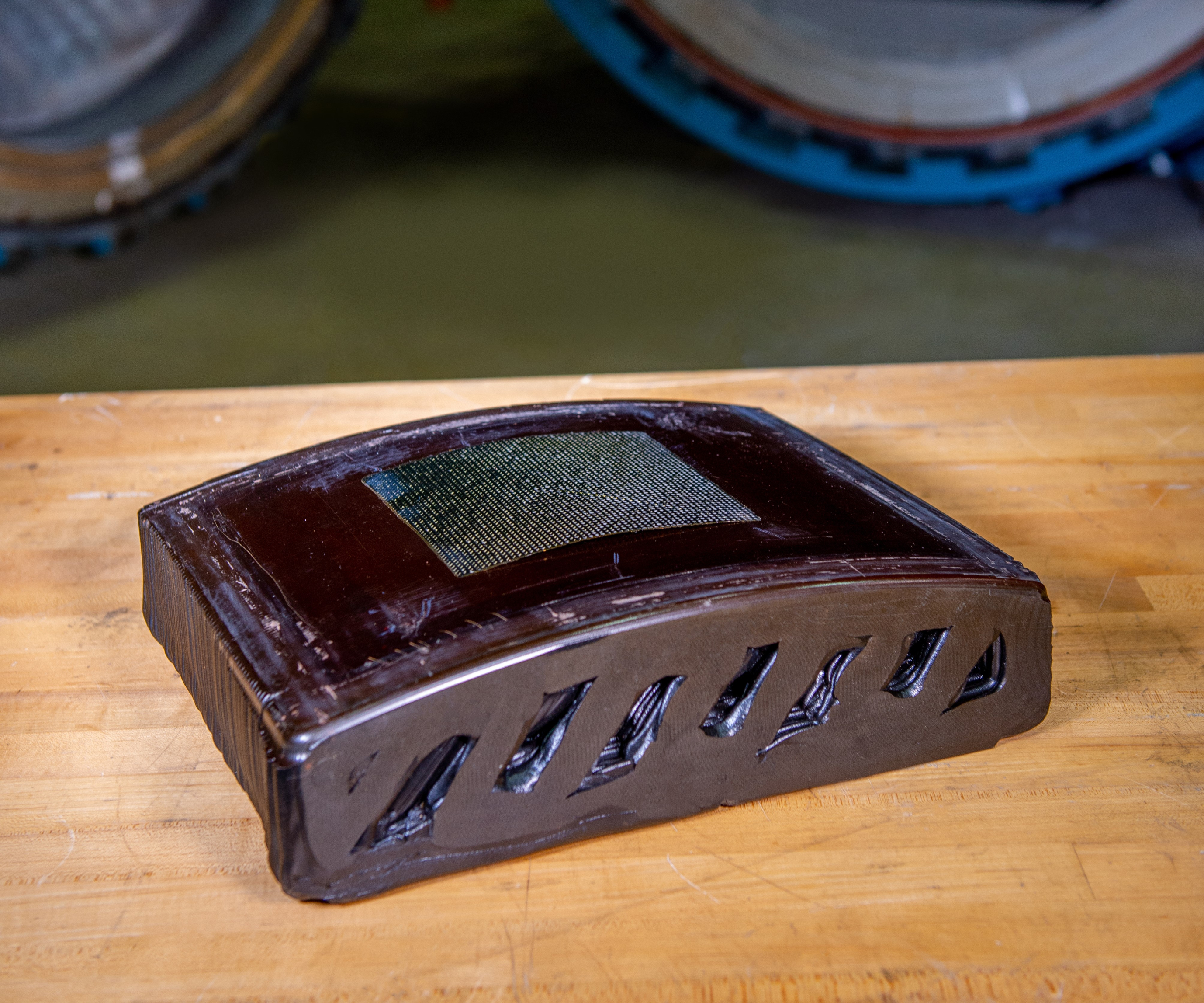
Figure 3. Post-machined tool made with Thermocomp AM EZ006EXAR1 compound.
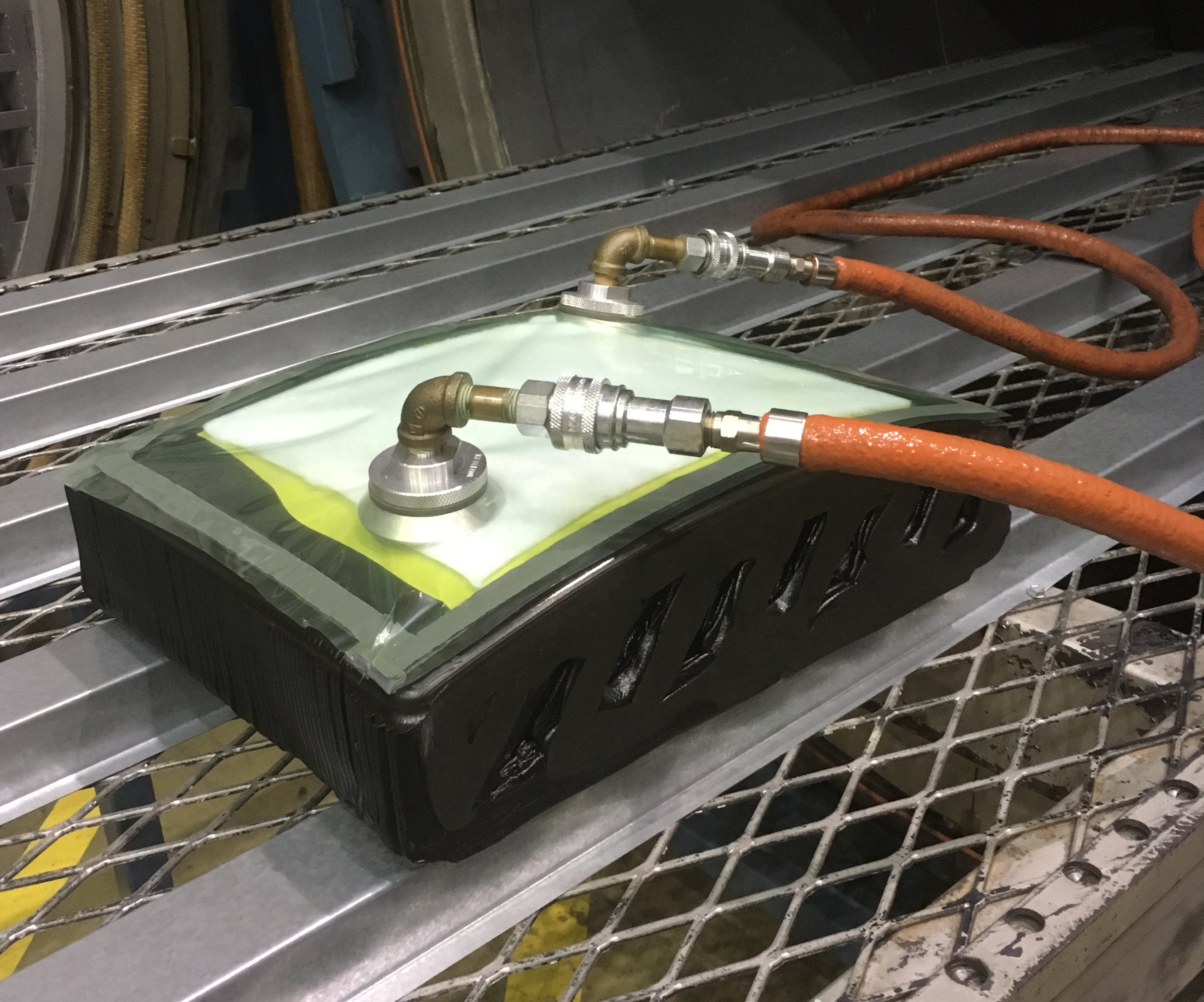
Figure 4. Tool setup prior to autoclaving.
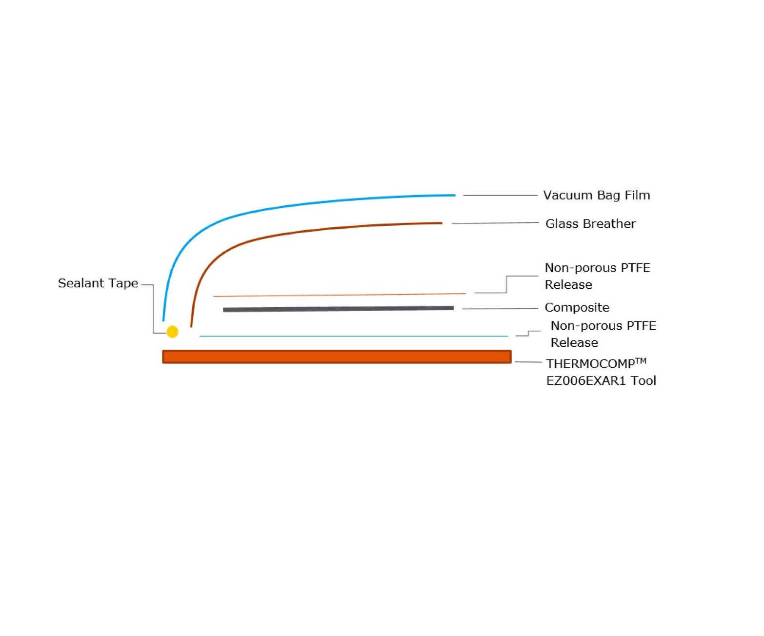
Figure 5. Layup construction of prepreg material.
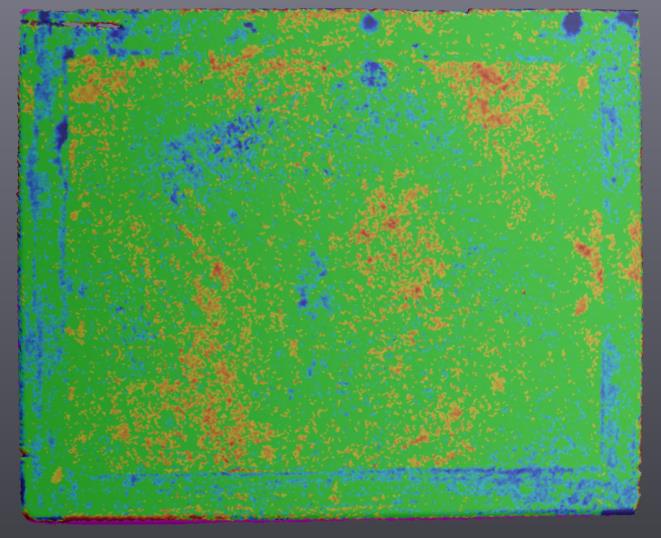
Figure 9. Tooling surface scan after 20 cure cycles, as compared to initial baseline, using 0.001 inches as the acceptance threshold. Analysis of the scan revealed the percentage of tooling surface within ±0.004 inches of the baseline scan conducted after the other phase testing was completed and is depicted by the green shading found in this figure. Red indicates an outward movement, while blue indicates an inward movement.


SABIC and the University of Dayton Research Institute have partnered on a project exploring the potential of using large-format additive manufacturing technology for creating autoclave tooling used in manufacturing aerospace composite parts.
In comparison to LFAM, CNC machining of metal to create autoclave tooling—the traditional approach—has upfront costs associated with both the material and the CNC time, as well as additional cost for design changes. The use of LFAM to create similar tools can help to reduce expense and time to create low volume, complex tools more quickly. Due to the increased print speed of LFAM versus CNC metal-machining, multiple design iterations can be 3D printed in the time that it would take to produce a single CNC metal tool. In addition, the ability to quickly 3D print a tool from a computer-generated file eliminates the need and cost for long-term storage of the tool, as a new tool can be printed if necessary.


Large-format additive manufacturing involving plastic materials performs 3D printing using plastic pellets melted via an extrusion barrel and extruded layer by layer to build a part. Since the LFAM process is pellet-fed, there is broad availability in feedstock, including filled thermoplastic compounds containing glass fiber, carbon fiber, minerals, etc. that give the designer the ability to provide strength and a coefficient of thermal expansion that cannot be achieved with unfilled resins. As parts get larger, the need for reinforcement becomes more critical to help maintain structure, both during printing and in final use.
LFAM provides the ability to print large parts not viable with smaller printing processes and enables the creation of complex geometric parts that would be difficult to produce using conventional processes such as injection molding. LFAM printing speeds enable fast prototypes and multiple iterations of a design, reducing development cycle times and lead times compared to traditional production methods. Low volume, customized production is possible with lower cost and time investment when viewed next to larger volume production methods that require upfront investment.
Finding the right resin/filler system combination for the rigorous autoclave environment became the challenge. To replace metal tools with LFAM tools, the material had to print well and also withstand the loads, temperature cycles and dimensional requirements needed for use. Dimensional stability of the printed tool was critical, as movement of the tool could have a negative effect on final part quality.
Selection
The autoclave tool referenced in this study required the ability to withstand an autoclave cycle at 350°F while under 85-90 psi pressure. The tool needed to withstand greater than 10 autoclave cycles, maintain vacuum integrity, and maintain dimensional profile tolerances of ±0.005 inches over the tooling surface before, during and after autoclaving.
For the tool’s material, the LNP Thermocomp AM EZ006EXAR1 compound was chosen because it provides a combination of Ultem resin, a well-known high temperature material used in aerospace applications, and a filler package for dimensional control.
The tool geometry selected for this study, one relevant to a wide range of industries and applications, is similar to parts used on military aircrafts. An oversized tool was designed to allow for the surface to be machined to the required final dimensions (see Figure 1).
The tool was printed at SABIC’s Polymer Processing Development Center (PPDC) in Pittsfield, Massachusetts, on Cincinnati Incorporated’s Big Area Additive Manufacturing (BAAM) machine.
The BAAM printer contains a single screw extruder with six heating zones. Each zone is capable of heating to 500°C and the screw is designed to process filled polymeric compounds. The 140-layer tool was printed in 2.5 hours using a double outer wall with a staggered line infill pattern (see Figure 2).
The LNP Thermocomp AM EZ006EXAR1 compound demonstrated consistent and stable bead dimensions during printing with a smooth surface on the bead. The overall part exhibited low levels of warping when examined after printing.
Because large-format additive manufacturing technology can print to a near-net-shape, only one machining operation was required to achieve final dimensions (see Figure 3). The machined tool was sent to Tru-Design in Knoxville, Tennessee for application of their TD Seal HT coating. Developed as a thin, spray-on coating that can bond to high temperature LFAM feedstocks without cracking during autoclave cycling, TD Seat HT, serves to provide a smooth and vacuum-tight tool surface.
Testing
Phase 1
The University of Dayton Research Institute performed the initial Phase 1 testing of the completed tool. During Phase 1 scanning and vacuum testing, no significant vacuum loss was detected, indicating that the TD Seal HT provided a good sealing surface.
Phase 2
The second phase of testing, autoclave cycling, was completed at SABIC’s PPDC facility. During each cycle, a composite layup was placed on the tool (see Figure 4) and autoclaved to cure the composite. The composite lay-up and autoclave process included two plies of RM 2005 epoxy/carbon prepreg, manufactured by Renegade Materials Corporation, and was laid up as illustrated in Figure 5.
For each autoclave cycle, the steps below were followed:
- Vacuum hold for 60 minutes at room temperature.
- Heat 5°F per minute to 350°F ±10°F with 30 ±5 psig applied pressure until temperature reaches 225°F ±5°F.
- After the temperature goes beyond 225°F, apply 85 ±5 psig autoclave pressure and vent to atmosphere.
- Hold temperature at 350°F ±5°F for 120-135 minutes.
- Cool at 5°F per minute. When temperature is below 302°F, release pressure.
This process was repeated five times. After the fifth cycle, the tool was scanned using a Creaform HandyScan 3D handheld scanner. Analysis of the scan revealed that 99.7% of the tooling surface was within ±0.004 inches of the baseline scan conducted after the Phase 1 testing was completed (depicted by the green shading found in Figure 9). This percentage represents three standard deviations of data distribution from the baseline.
Phase 3
The tool was subjected to an additional five autoclave cycles during Phase 3. The same procedure was used, but the autoclave pressure was increased to 85 psig from 100 psig. Once the cycles were completed, the tool was scanned again.
In comparison to the baseline scan, the results were similar to those seen after the first five autoclave cycles: 99.7% of the tooling surface was within ±0.004 inches of the baseline scan.
Phase 4
In Phase 4, the tool was exposed to a final 10 cycles of autoclaving using the same lay-up as in the Phase 3 testing. Once all of the cycles were completed, the tool was scanned again and compared to the original baseline. As seen in the previous comparisons, 99.7% of the tooling surface was within ±0.004 inches of the original baseline scan.
Results
After the first five autoclave cycles, the tool exhibited minimal movement of ±0.004 inches away from the baseline. An additional 15 cycles showed similar scans, indicating that the initial movement that occurred was isolated to the first five autoclave cycles. After the first five autoclave cycles, the tool stabilized and did not continue to move during the remaining autoclave cycling testing. For the purposes of this study, only permanent deformation of the tool was recorded, not temporary movement that might occur during the actual autoclave process.
Only when lowering the acceptance threshold to 0.001 inches could the direction of the tool surface movement be seen (Figure 9). No distinctive trend was found other than an inward movement around the periphery of the tool, which is most likely a result of surface wear resulting from vacuum tape scraping and removal.
Large-format additive manufacturing is a viable process for producing autoclave tooling.
The final results indicated that, after five standard 350°F autoclave cycles, the tooling showed movement of less than ±0.004 inches. This is within the ±0.005-inch tolerance common in the aerospace industry. Almost no subsequent movement occurred after an additional 15 cycles.
While the authors and team recognize the need, moving forward, to quantify the actual time and cost savings using LFAM versus incumbent tooling approaches in future work, initial estimates show significant savings in both time and cost.
This study confirms that large-format additive manufacturing is a viable process for producing autoclave tooling that can withstand at least 20 standard autoclave cycles without introducing dimensional inaccuracies into the part.


Related Content

Video: Reinforcing (and Joining) Parts After 3D Printing
Reinforce 3D has developed a method that can be applied to strengthen 3D printed parts by feeding continuous fiber and resin through them. The technique also enables joining parts of various materials and manufacturing methods.
Read More8 Social Media Posts About Additive Manufacturing: AM Radio #34
Cost savings, modifications, large-format AM and more. In this episode of AM Radio, we discuss what people are saying about additive manufacturing on social media.
Read More
Aircraft Ducts 3D Printed in Composite Instead of Metal: The Cool Parts Show #68
Eaton’s new reinforced PEKK, tailored to aircraft applications, provides a cheaper and faster way to make ducts compared to formed aluminum.
Read More
Additive for Composites and Composites for Additive: AM Radio #17
CompositesWorld’s Jeff Sloan joins Peter Zelinski in an episode of the AM Radio podcast about how composites and 3D printing are changing one another.
Read MoreRead Next

Using 3D Printing for Composite Molds and Tools: The Trend Continues
3D printing is becoming more common in the aerospace tooling realm. Production tooling can be made quickly and on-demand, which helps the tooling industry keep pace with accelerating composite part design cycles and demand for faster overall part processing speeds.
Read More
At General Atomics, Do Unmanned Aerial Systems Reveal the Future of Aircraft Manufacturing?
The maker of the Predator and SkyGuardian remote aircraft can implement additive manufacturing more rapidly and widely than the makers of other types of planes. The role of 3D printing in current and future UAS components hints at how far AM can go to save cost and time in aircraft production and design.
Read More
4 Ways the Education and Training Challenge Is Different for Additive Manufacturing
The advance of additive manufacturing means we need more professionals educated in AM technology.
Read More