
Choosing the Best Abrasive Finishing Process for 3D Printed Parts
Studies have shown that abrasive finishing is flexible enough to finish 3D printed parts with complex geometries and difficult-to-machine materials, although the best process depends on a number of factors.


For metal production parts made through additive manufacturing (AM), post-process finishing is often required, especially on functional surfaces. Abrasive finishing, including grinding and polishing, has the capability to finish conventional as well as parts made additively — that is, 3D-printed parts. Compared with machining such as milling and other alternative finishing processes, grinding has advantages for producing tight tolerances, fine finish and desired compressive residual stress in the ground surface layer. The advantages can become more substantial for difficult-to-machine materials commonly used in 3D printing, because the self-sharpening property of abrasive grains extends abrasive tool life longer than that of other cutting tools. Grinding wheels can be prepared with complex forms for finishing 3D-printed Inconel 718 and titanium 6-4 parts. Using a grinding process with a pre-formed wheel is an effective way to finish a relatively large batch of parts. In addition to precision grinding, abrasive tools can be also used for free-form finishing in manual or robotic mode.
For small-batch operations, users of metal 3D printing are investigating how to apply grinding with flexibility for complex part geometry. Norton│Saint-Gobain Abrasives partnered with the Manufacturing Technology Center (MTC) in Coventry, United Kingdom to study the use of CNC grinding with mounted-point wheels and free-form finishing with abrasive tools to finish 3D printed parts.


CNC Grinding with Mounted-Point Wheels
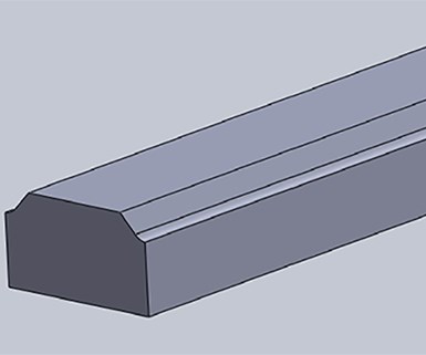
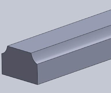
Figure 1: Tests conducted on these Inconel 718 3D printed parts with chamfered and curved surfaces showed that mounted-point electroplated cBN grinding wheels produce good surface finishes and have long wheel life, making them a good option for finishing 3D printed parts with tight tolerances that are made of difficult-to-machine materials. Images provided by Norton Saint Gobain
Electroplated or vitrified cBN grinding wheels are widely used for grinding Inconel 718 (IN718) parts, with processes ranging from heavy stock removal to precision finishing for tight tolerances. In this study, researchers selected a mounted-point cBN wheel to demonstrate the feasibility of CNC grinding on 3D printed IN718 parts. The mounted-point wheel was an electroplated ball-end wheel that was 6.35 mm diameter and had 100 grit cBN abrasive.
A RenAM500Q laser powder bed machine from Renishaw produced the IN718 parts with chamfered and curved surfaces, shown in Figure 1. After printing, the parts were heat treated for a post-build stress relieving cycle at 900°C for 45 minutes, and then nitrogen cooled to room temperature. Following heat treatment, researchers found the average surface area roughness (Sa) to be about 14 micrometers, as measured by an Alicona Infinite Focus SL focus variation microscope. In this study, Sa measurement is used to characterize surface finish because it represents the roughness of the whole surface and is independent of measurement direction, whereas Ra measurement along a line may be affected by anisotropic surface texture.
The MTC conducted the CNC grinding experiments. Table 1 lists the grinding conditions, where the coolant was 5% emulsion (water soluble). The selection of emulsion coolant was to facilitate part cleaning after grinding. Although cBN wheels perform better with straight oil coolant, it makes part cleaning difficult, particularly for complex shapes and difficult-to-access features typical of 3D printed parts. Therefore, oil was not considered for this study.
|
Grinding wheel |
Coolant |
Spindle speed |
Feed rate |
Depth of cut (mm) |
|
Electroplated cBN wheel |
5% emulsion |
18,000 rpm |
150 mm/min |
0.1 mm, 0.2 mm |
Table 1: Grinding wheel and process condition in the CNC grinding experiment
The IN718 parts with chamfered and curved surfaces were successfully ground to a surface finish of 1.2 - 1.5 micrometer Sa. During the grinding experiment, an automated Blum tool measurement system installed on the machine tool measured the wear of the grinding wheel. While the tool measurement system was originally developed for milling and turning tools, this study demonstrated it can be adapted for grinding wheels. Integration of this type of measurement with the machine controller enables automated wheel wear compensation.
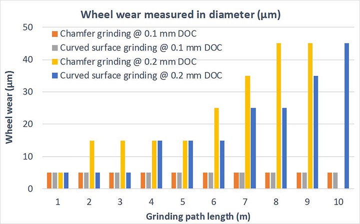
Figure 2: This graph of measured wheel wear and grinding path length shows that with a 0.2 mm depth of cut, tool wear was rapid on both chamfered and curved surfaces, and surface finish deteriorated as the wheel wore down. Decreasing the depth of cut to 0.1 mm significantly reduced wheel wear.
Figure 2 shows the measured wheel wear as a function of grinding path length. At a 0.2 mm depth of cut and 150 mm/min feed rate, tool wear was relatively rapid tool when grinding both the chamfered and curved surfaces. Surface finish deteriorated when wheel diameter reduction became approximately 45 micrometers, after about 8 meters of grinding distance. At the same feed rate, decreasing the depth of cut from 0.2 to 0.1 mm significantly reduced wheel wear to less than 10 micrometers after 10 meters of grinding.
Researchers also performed milling experiments using a TiAlN coated carbide tool and process conditions recommended by Hoffmann Group (174 mm/min feed rate and 0.2 mm depth of cut). These studies showed similar surface finish and tool wear to grinding. While milling can achieve larger depth of cut (0.2 mm vs. 0.1 mm), grinding has a potential cost advantage: the grinding wheel used in the study was only about $15, compared with about $50 for the corresponding milling tool.
The studies showed electroplated cBN wheels can achieve good surface finish and long life when grinding IN718 and other difficult-to-machine materials. The compatibility with water soluble coolant and in-situ tool wear monitoring makes mounted-point cBN wheels an attractive choice for finishing 3D-printed parts. The advantage of grinding over milling or other machining is further highlighted on hardened metals. For a 3D-printed part with near-net shape, post-processing can be optimized by directly heat-treating printed parts without machining at soft state, and then finishing the heat-treated parts with grinding.
Free-Form Finishing with Abrasive Tools
Robotic or manual finishing is an alternative to grinding for parts with
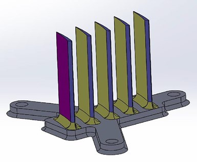
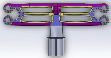
Figure 3: Saint-Gobain Abrasives and the Manufacturing Technology Center used these 3D-printed IN718 parts, which represent shapes commonly found in the aerospace and tooling industries, to test free-form finishing with abrasive tools on parts with complex profiles but no tight dimensional tolerances.
complex profiles but no tight dimensional tolerances. To study this, researchers printed two IN718 parts (shown in Figure 3) to represent shapes commonly found in the aerospace and tooling industries and heat-treated them as described in the preceding section. Supports were required to print the rib/strut, as shown in Figure 4A. They were removed with hand tools, such as a flush cutter, leaving marks on the part surface.
For relatively large free-form surfaces, studies found that a file belt is the best tool due to its conformity to surface profile and flexibility. A coated file belt with medium grain size (P60) achieved good material removal rate and long life on the as-printed surface. A non-woven belt was then used to produce good surface finish. Quick-change disc and spiral rolls were also tested on the free-form surface, but did not perform as well as the file belt. A fiber disc was found to be less reliant on the tool contact angle and couldn’t reach constrained areas, resulting in a sudden change of material removal and finish on profiled surfaces. A spiral roll could access small areas, but couldn’t maintain stable contact with concave surfaces, resulting in tool vibration and uneven finish.
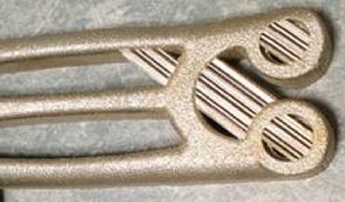
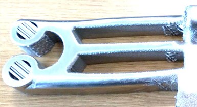
Figure 4: This rib/strut required supports while printing, which were removed with hand tools. The external edges were finished with a unified non-woven wheel and a cotton fiber mounted-point wheel, while the interior surfaces were rough ground with a spiral roll and finished with a non-woven unitized wheel.
For external or easy-to-access surfaces with contoured profiles, a unified non-woven wheel and a cotton fiber mounted-point wheel were able to finish the surfaces without significantly altering the part geometry. However, both tools wore down quickly when applied directly on the rough, as-printed surface. Thus, it is recommended to use a coated flap wheel or spiral roll as the first step on the as-printed surface. A non-woven flap wheel can be then used to finish relatively large surfaces, and unified and mounted-point wheels can be used for intricate or small areas.
Figures 4 and 5 compare the as-printed and finished parts. The abrasive
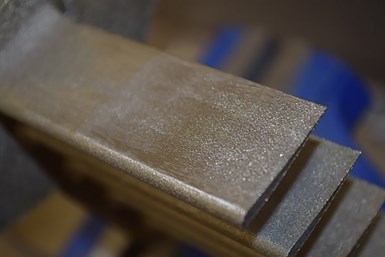
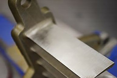
Figure 5: Because unified non-woven wheels and cotton fiber mounted-point wheels were found to wear down quickly when finishing the blade edge, the study suggests using a coated flap wheel or spiral roll first on the as-printed surface.
processes described above achieved significant improvement on surface finish. Surface profile and roughness measurements shown in Figure 6 indicate a reduction of Sa from about 12 micrometers on the as-printed surface to approximately 2 micrometers on the finished surface.
A two-step process is recommended to first rapidly remove defects or other rough surface features with a coarse grit abrasive product. The surface can then be finished with a more compliant abrasive product. Non-woven abrasive products made with nylon fibers impregnated with abrasive grains are an ideal choice for the free-form finishing of profiled surfaces, as they can conform to the part surface and uniformly finish it with minimal distortion to its geometry.
For free-form finishing, there is a wide range of belt, discs and mounted-point wheels. Table 2 summarizes a general guidance for selecting proper abrasive products based on common features on 3D printed parts. Ceramic abrasives are recommended for stainless steels and superalloys, and SiC or Zirconia abrasives for titanium and aluminum.
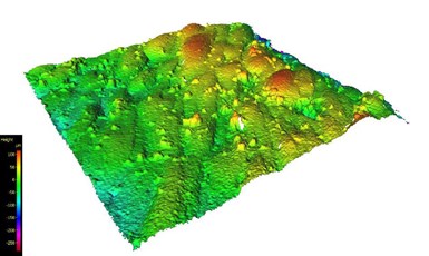
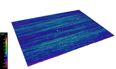
Figure 6: The finishing method in the study reduced surface finish from 12 micrometers Sa to approximately 2 micrometers Sa, as seen here.
The abrasive products shown in Table 2 are used with portable power tools, including mini right-angle grinders, die grinders and file belt grinders. The light weight, small size and flexibility of portable abrasive tools allow different configurations, such as bringing tools to stationary parts, bringing parts to tools, and simultaneously working with both tools and parts. Multiple abrasive tools can be set up on a workstation to finish a variety of complex features. Using CAD drawings and other part information from the upstream (3D printing) process, selection of abrasive tools and finishing processes can be fully automated with CNC machines and robotic cells, which can ensure consistent results with the help of in-process force measurement, vision sensors and closed-loop control mechanisms.
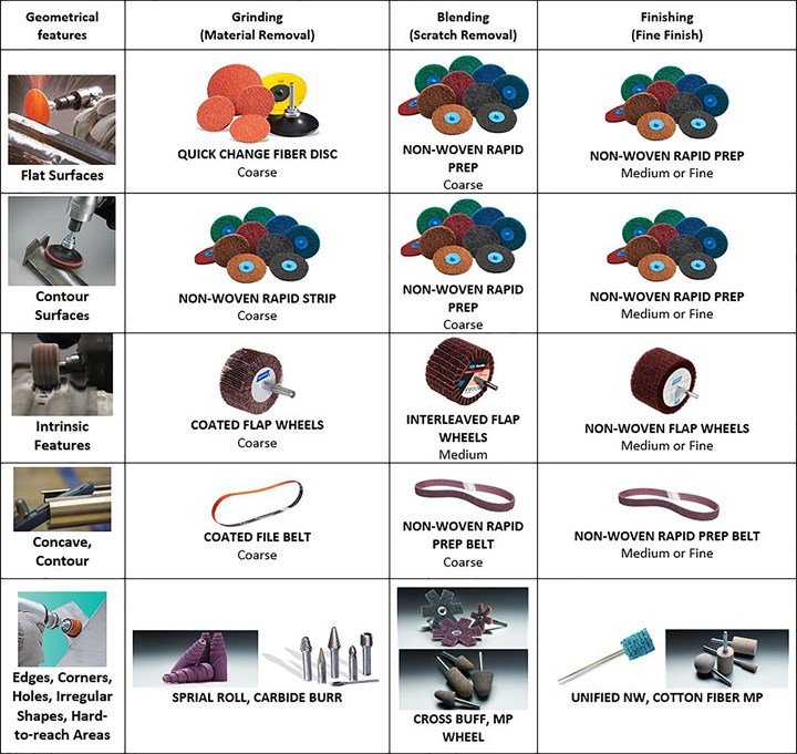
Table 2: This table shows which abrasive products work best for grinding, blending and finishing different types of features.


Read Next

Meeting the Machining Challenges of Additive Manufacturing
You can 3D print the part, but can you finish it? Here is how to overcome the challenge of part deflection in the machining of lightweight, complex AM parts.
Read More
Growing Closer: Machine Shops and 3D Printing for Production
Machining a large 3D-printed part for aerospace composite tooling is fundamentally different than manufacturing the part traditionally. Baker Industries knows this first-hand.
Read More
Grind to Finish: A Postprocessing Solution for Additive Manufacturing
3D printed metal parts typically feature little stock remaining for finishing. Grinding is potentially an effective solution for meeting final tolerances. An abrasive technology provider investigates grinding as a complement to AM.
Read More