
.jpg;width=70;height=70;mode=crop;format=webp)


All around us in our homes, vehicles and other physical products, networks of ducts and vents keep air moving to cool or heat these systems. Not all ducts operate efficiently, however. Many are actually larger than they need to be for the way air actually moves, requiring more powerful fans and consuming more energy than necessary.
A joint project between Siemens and HP resolved this issue with an air duct inside the latter’s Multi Jet Fusion polymer 3D printer. Fluid dynamics simulation revealed the true paths that air was taking through this duct, allowing the teams to redesign the part around these streams. The result, discussed in this episode of The Cool Parts Show, is a more efficient air duct with a computer-generated design that surprised even its creators. This episode was originally broadcast live on December 8, 2020, through the IMTS spark platform. | This episode of The Cool Parts Show brought to you by Carpenter Additive
The Cool Parts Show is a video series from Additive Manufacturing Media that explores the what, how and why of unusual 3D printed parts. Watch more here.
Have a cool part to share? Email us.
Resources and Links
- The basics of Multi Jet Fusion (MJF)
- More on redesigning the “Mighty Duct” (sponsored content)
- Another Cool Part made through MJF
- More cases of assembly consolidation
Transcript
Stephanie Hendrixson
On this episode of The Cool Parts Show, 3D printing and computational fluid dynamics come together to enable more efficient airflow.
Peter Zelinski
This episode was originally broadcast live within the IMTS Spark platform. It has some lovable live broadcast roughness to it. Hope you enjoy.
The Cool Parts Show is brought to you by Carpenter Additive. The company's Athens, Alabama, Emerging Technology Center is an end-to-end additive manufacturing production facility with everything from material development to postprocessing under one roof, ready to help you with your next metal 3D printing job. Check them out at CarpenterAdditive.com. Now back to the show.
Welcome to The Cool Parts Show, our first-ever live episode of the show.
Stephanie Hendrixson
That's right. We are going to be talking today with some of our experts. They're here to answer our questions, but more importantly, they're going to be here to answer your questions.
Peter Zelinski
The Cool Parts Show. If you're new to the show, here is the essence of our show. Every episode we talk about a cool 3D printed part and, end use part doing an actual job that was made through 3D printing, through additive manufacturing. We talk about how that part was made, what it means, what it means for manufacturing. We talk to the people who were involved in making it. Stephanie, what is the cool part you have for us today?
Stephanie Hendrixson
The cool part we're going to be talking about today is this one right here. This is an air duct.
Peter Zelinski
An air duct. That's another thing about the essence of this show is we appreciate underappreciated components. If you don't think an air duct is cool, you're about to. Tell us about this duct.
Stephanie Hendrixson
This air duct is cool for a couple of reasons. This is an example of 3D printing winning out against injection molding. It's an example of assembly consolidation. It's redesigned through simulation, fluid dynamics specifically. It's two different companies collaborating, working together, and it's 3D printing helping 3D printing.
Peter Zelinski
That's a lot, lot of questions. 3D printing, helping 3D printing talk about that.
Stephanie Hendrixson
This air duct is part of this 3D printed assembly. They're both 3D printed, and they go inside of the same kind of 3D printer that was used to make them. So these are all parts for the Multi Jet Fusion system from HP.
Peter Zelinski
You said companies working together, HP is obviously one of them. What's the other one?
Stephanie Hendrixson
The other one involved is Siemens.
Peter Zelinski
What's their role?
Stephanie Hendrixson
Siemens is a major software company, their software was used to simulate the fluid dynamics simulate the air going through this air duct to arrive at this design, also for build preparation and print simulation.
Peter Zelinski
Multi Jet Fusion. Let's talk about that. A polymer 3D printing process from HP, uses a powder bed, it uses agent. It involves rapid melting, rapid cooling to solidify the part layer by layer. The thing about Multi Jet Fusion is, it's fast. It is a production 3D printing process, and it is possible to nest a variety of parts inside the build nest within the three-dimensional box shape of the build volume. This is a 3D printing process at production speed and at production scale.
Stephanie Hendrixson
Yes, and part of that build preparation simulation was figuring out how to nest a bunch of these parts together. If you look on the floor next to your chair, you have an example of what one of these builds looks like.
Peter Zelinski
This is the build. Oh, I’m obscured. Alright this volume of parts made through 3D printing, made in one 3D printing build, and you said this is 3D printing winning out over injection molding. They could have manufactured this through injection molding, why 3D printing instead?
Stephanie Hendrixson
Good question. I mentioned assembly consolidation earlier, and I want to show you an earlier version of this part. This is a simpler looking version that's also 3D printed, but originally HP was thinking they were going to injection mold this air duct. The issue was that this would have been like six different injection molded parts that then they would have to assemble together. So they originally went with 3D printing with this design as a way of avoiding all that assembly and tooling because they could print it as one piece.
Peter Zelinski
Let's talk about that. Previously injection molded, in how many different parts did you say?
Stephanie Hendrixson
Six.
Peter Zelinski
Six different components. Meaning six different mold tools, and then assembly work on top of that, there was work labor involved in in doing the assembly. If they get away from injection molding that means no mold tooling needed, no assembly work needed, and because molding is a high-volume process, they would have had to make big batches of each of those different six parts and inventory all of those. Getting away from tooling, getting away from assembly, getting away from inventory, that was enough to justify 3D printing. And yet, there’s still this, which is weird. Can we talk about the design weirdness?
Stephanie Hendrixson
Yeah, absolutely.
Peter Zelinski
Here's my guess at what happened here. There's no tool, no mold tooling, and no assembly interfaces, or much fewer assembly interfaces because it's all printed as a solid piece. You get away from that hardware and the commitment that it requires from you, and you get this new freedom to refine the design, to tweak the design. They went way beyond just tweaking. What made them decide that a change was in order here to the form of this duct?
Stephanie Hendrixson
Good question. I will just say about this simpler design that we have here, this one works. If you have a Multi Jet Fusion printer in your facility, this is probably the air duct that it has. What happened was HP and Siemens came together, they were looking for good use cases of simulation used in combination with 3D printing. They considered a lot of different parts, but one of the ones, you know, on the conference room table was this air duct. So the goal of this project was not to make the craziest looking air duct that we possibly can, even though it does look pretty crazy. It was, let's take something that already works and see how much more efficient we could make it at doing its job at moving air through a system.
Peter Zelinski
This kind of blows my mind. To do an air duct, you feel like all you need is to get a big box that you can flow air through, right. What you're saying, and what this seems to be revealing, is there are all these invisible inefficiencies within a duct like that. How did they get to this form? How did they decide on that?
Stephanie Hendrixson
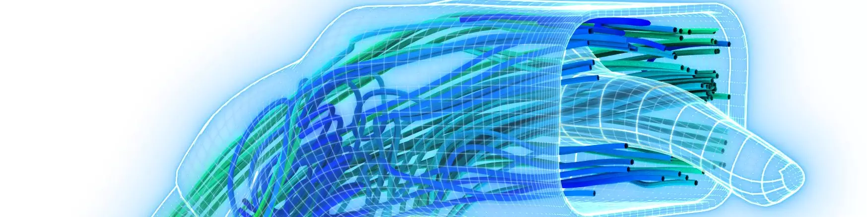
Siemens has a fluid dynamics simulation program called Star CCM+, that's what they used to kind of analyze the way that the air wanted to flow through this envelope. It's basically topology optimization, but instead of optimizing for weight reduction, or material savings, like we've seen in other cases, optimizing for the way that the air wants to flow. Like you said, instead of one big space for the air to move, there are now these four individual channels that basically represent you know what the most efficient path is for the air to travel through this geometry.
Peter Zelinski
This is so crazy, you said how the air wants to flow right? This is a picture and a physical construction of how the air wants to flow, and nobody could ever see this before, nobody could ever see the waste that was resulting from the air being forced into spaces it didn't want to go to. What if all ducts were like this? How much energy are we losing?
Stephanie Hendrixson
Something I think is interesting about this is that this is a geometry that a human would probably never come up with, a human would design this. This is something that really, you need software to arrive at that.
Peter Zelinski
That's what I'm seeing here. This success is really two different technologies coming together. There's the computational power of the fluid dynamics model of the airflow this way, and that resulted in a form no designer would have ever constructed. Then there's 3D printing, digital manufacturing, allowing the production of a form that couldn't be made any other way. These two technologies have found each other now, the computational, the 3D printing. Now that they've come together, will more ducts look this way?
Stephanie Hendrixson
I think that's possible. I mean, think about all the air ducts that are all around us in our houses, in our cars, and in our 2D inkjet printers. I'm sure there are lots of places where we're wasting energy by moving air in inefficient ways.
Peter Zelinski
The air duct leading away from my air conditioner, if it rattles, that's a sign of energy being wasted because the air doesn't want to flow that way. Do HP and Siemens know how much energy savings they've won by going to this design?
Stephanie Hendrixson
That is a great question and I think now would be the perfect time to bring in our experts. Joining us today are Ashley Eckhoff from Siemens, and Luis Baldez from HP, both of whom worked on this project. Ashley, Luis, thank you for joining us.
Ashley Eckhoff
It's our pleasure.
Luis Baldez
Our pleasure.
Stephanie Hendrixson
You have been listening in on the conversation so far and we're at the point where we want to ask you some questions. Pete just asked about the performance improvement. How much better is this air duct at moving air than this one?
Ashley Eckhoff
Do you want me to take that, Luis?
Luis Baldez
Yeah, go ahead.
Ashley Eckhoff
As you guys described the way this system worked, we started out with a simulation. It's a simulation driven part. In order to make the system work the way we wanted to, we started out with a simulation of the original duct, we needed a baseline. We simulated that and understood what the flow was in that system. Then we created the new version which I'm sure we'll get to here in a minute, but that version we simulated as well. Our predictions were that it would be about 22%, 22.3% more efficient than the original duct, and we weren't going to know that for sure until the parts were printed. Once they were printed, Luis and his team took over right, Luis?
Luis Baldez
Yeah, exactly. When I first saw that saw the results, I was like wow, hang on, that can't be possible and effectively I went into the lab and then we measured the amount of air that we're pushing on one side and the amount of air that was coming out on the other side. Effectively we saw 22% improvement as predicted by the software. Which was kind of very surprising to everybody in the project.
Ashley Eckhoff
It was a really cool moment for all of us.
Peter Zelinski
It never occurred to me that something as simple as an air duct could be wasting so much energy. I guess Ashley, can you talk about the simulation software? Tell us a little more about that, how does it work?
Ashley Eckhoff
Sure, as you guys mentioned it's based on topology optimization. If anybody's seen all kinds of topology, optimized parts, right, they're kind of these organic, H.R. Giger-looking things that people make, and those are all designed by software. This is using the same technique, but applying it to a different goal. As Stephanie mentioned earlier, most of those parts are designed to optimize material usage or to minimize weight. In this case, we're trying to optimize the flow of a fluid through a volume. We start out with the overall volume the fluid can possibly take up. We used the volume of the interior of the original duct as sort of our envelope. It works the same way as other topology optimized systems do. You take that volume and you start chipping away, and throwing away all the pieces that you don't need. The reason you do that for fluid optimization is because if you think of dropping a leaf in a stream, sometimes it's going to rock it down that stream if it's in the right path, and it's going to go really fast. Other times, it may get swallowed up in the vortex over on the side somewhere, and it's those vortexes that we want to get rid of. They basically slow down the air through the system, they cause a recirculation and that's what the software does. It takes those areas and throws those areas away so that you're basically left with the optimal stream as the only path.
Stephanie Hendrixson
Ashley, I think that the fluid dynamics software led you towards this geometry, but I think you still had to do some design tweaks Is that right?
Ashley Eckhoff
Yeah, so what comes out of Star CCM+, and any other system that works this way is the interior volume. It's the area inside the duct the optimized area inside the duct, but I still have to make a thin part out of that in the duct area. You have to do some offsets, you have to do some smoothing, and things like that. It's not just a one button push and boom, here's your part. There's definitely some design work in there, and one thing to notice is that it was kind of funny the first time we made this part, we did the offsets and I wasn't paying very much attention at the time because we were kind of in a hurry, we had a deadline. I wasn't paying attention to the wall thickness and the first one we printed when it where I'd let the wall thickness get to thin, and that was my own fault. I forgot to run the check before I sent the geometry to Luis, and you know you run the check, you figure out that area has a small leak in what you printed, and it turns out right the next time so you know it's one of those things. It's trial and error.
Peter Zelinski
I guess I want to hear about just sort of the mechanics of the build. Luis, like how many parts? Do you build in one batch? And what's the build time?
Luis Baldez
Yeah, for this particular part we're able to fit in about 26 parts in one build. In one build normally takes around 10 hours a day. 10 hours to print, plus a few hours to cool. In practical terms, you're getting about 26 parts if you do one shift a day, or 52 if you have two shifts a day.
Stephanie Hendrixson
Speaking of timelines, I'm curious about the kind of design and iteration process here. How long did it take you to arrive at this geometry from kind of starting with this one as your as your starting point?
Luis Baldez
Yeah, I always like to say that the mother of all expiration is the deadline. We had the original duct was designed by a mechanical engineer on our team. Normally this takes a few months to design, test, print another version. The whole cycle took about four months. In this case, we were able to come up with this design in about one month. Which is quite significant, because not only do you reduce the time to the time, but you landed on a solution that is much better than what you have done on your own. That was one of the highlights of the project.
Peter Zelinski
Here's a question for maybe both of you. What you're describing here is a learning process, and you take something as innocuous as an air duct, and even you guys, the 3D printing experts, you're learning things as you go, you're figuring out how to design it better, or how to make it better and I guess where that gets me to is, is this part a good use for additive manufacturing? I guess larger than that, what does this part show about what kind of opportunities are available when you rely on 3D printing as the production process.
Ashley Eckhoff
Luis actually really described as well. Once we started thinking about all these other applications for this same technology. As you guys were talking earlier, are there any place where air flows, vacuums, fan systems, any type of ductwork in a car, or train, or a plane. Even more than that, since the HP printers print fluid-type material, you can do any type of fluid, so it could be optimizing the cooling in a battery pack for an electric vehicle. It's anything where a fluid is moving, you can theoretically use this system to improve the amount of flow through a system. It's really cool because it's kind of this inflection point that's coming where design is shifting from a human-centric endeavor to a software system-centric endeavor. Luis talked about his engineer lovingly crafting this beautiful duct part. The original one that he worked really hard on, made all these nice radii, it looks beautiful, and then that takes four months. You throw it into the system and the system takes four weeks with me mucking around tweaking with it at the end to do something that's actually optimal. It's a really interesting time to be designing these things, and additive manufacturing is the technology that enables it all to happen.
Luis Baldez
The couple of things all highlighted to me, which were very significant, it happens over and over, and I bet the same thing happens in every Cool Parts Show, which is the importance of design. That's really critical to get the benefits of additive manufacturing. It takes a very different approach of how you think about the function that you want to achieve, and you got to have that super clear in your mind. Then you figure out the geometry at the end. That's one highlight. The second thing is not straightforward. In fact, you're right, I've been working on this for more than 10 years, then every time you need to get a lot of experts on simulation, on design, on printing and postprocessing, to actually come up with a part that is that is viable for production. This is where HP and the Siemens partnership come in. We did this once, we put it in our production line, but also reached out to customers and show what's possible. We're here to help if anybody in the audience can agree on this combination of technologies that can be used to solve a problem their own company.
Ashley Eckhoff
It's a real symbiosis between software and hardware. The software creating the initial design, and hardware system like HP is being able to print those at scale enough to go in the HP printers, right? It's real combination of those together that enable this sort of thing to happen.
Peter Zelinski
I think I got this. Start with this one air duct. This is an air duct for an HP Multi Jet Fusion 3D printer made by an HP Multi Jet Fusion 3D printer, and it was formerly injection molded in six different components. They were assembled together. The shift to 3D printing allowed for assembly consolidation, did away with mold tooling, did away with assembly, and did away with the need to inventory a lot of production parts as those six different components were previously made, and wait for assembly. All of those cost savings were sufficient to justify 3D printing as an alternative to injection molding, but once they got to that freedom from tooling, there was this wide-open window to start experimenting with the design. In sort of a thought experiment, they picked various parts of the printer to look for opportunities for design improvement, and this air duct was one selected. They used fluid flow simulation software Star CCM+ software from Siemens, to model the airflow and devise a geometry that sort of captures exactly the way that the air wants to flow. It resulted in this bizarre form no human could ever know to think of, and that no other production process could make, could only be made through 3D printing. Did I get that right?
Stephanie Hendrixson
Yeah, I think you covered it, and I think we've got a few minutes left to maybe take some questions from the audience.
Peter Zelinski
All right, Ashley and Luis, we do have audience questions. First question from the audience is, "What is the purpose of the little tongue sticking out of the end?" Your software told you this part should stick its tongue out and you guys just went with that? What is the purpose of the tongue?
Ashley Eckhoff
Yeah, the tongue. Honestly it's a geometry thing. I had to look at that things and rotate it around and try to figure out what that thing was. It's almost like it's turned inside out, but what that tongue does is it forces the air out of that region, the region where the tongue is the air can flow around the tongue, but it can't flow through the tongue. So the tongue is just one more little feature in there that's basically forcing the air into the optimal path. Frankly, none of us could have ever predicted that the geometry would turn out looking like that.
Peter Zelinski
The next question sort of asks about the challenges, a little bit about manufacturing choices made. Let's talk about this, here's what the question says, "It's definitely a cool part. A great demonstration of the technology. Can you articulate the cost savings 26 parts tying up a machine for 12 hours? What's the real cost if a manufacturer produced this part? What was the gain in airflow efficiency? Was that worth it, and did that help to justify the manufacturing?”
Luis Baldez
Yeah, when you in this is always a question what's the cost? What's the ROI? In this particular example, the fact that we were blowing more air on the output of the duct, it meant that our printer could go a little faster, so that duct exit, whatever it's doing, it's blowing some cold air into the printheads inside our 3D printers, and we need to have a cooling system so that you can run more reliably. In our case, we saw benefits and reliability. The second benefit is more related with a development time itself. We talked about going from four months to one month, and you know, in time to market or just the number of iterations that you skip, that had a benefit in and of itself. The other benefit is once you go to production, if you find a mistake, you can make that change any time. If you look broadly, apples-to-apples on what a molded part would cost and you look at just the amount of plastics, you may see that the benefit is unclear, but when you look at roughly across the product lifecycle, the benefits are much clearer. In our case, and I'll wrap up here, we could have chosen to use a cheaper or slower fan as the input, you get the same output on the other side. That could actually have been a cost reduction from a system perspective, because you don't need that powerful fan. Ashley, any other savings you might think of?
Ashley Eckhoff
Yeah, I think one interesting thing about this is that even though we concentrated on this one duct part, that duct is part of a larger system. What we did is we optimized the production of airflow through that system, but we only printed one part in that system. We were able to basically zone in on the part that we thought made the most improvement when we optimized it, and so you don't necessarily have to bite off the entire world here. You can make things into smaller chunks, and print those at a much lower cost and get yourself the improvements you need without theoretically paying extra money you necessarily don't need to do. But again, as Luis said, these are all things that kind of happened through the analysis and the design phase, but there are definitely things you can do that make additive more attractive from a cost per part perspective, even today.
Peter Zelinski
To our audience. Thank you for watching our first live episode of The Cool Parts Show. That went pretty well, don’t you think?
Stephanie Hendrixson
Yeah, I think so. We should do this again sometime.
Peter Zelinski
Alright, so if you're discovering The Cool Parts Show for the first time, where can you see our stuff?
Stephanie Hendrixson
You can find all the existing episodes of The Cool Parts Show on our YouTube channel or at thecoolpartsshow.com.
Peter Zelinski
Thank you to our sponsor, Carpenter Additive. Listen to additive manufacturing podcasts, attend webinars and learn more at CarpenterAdditive.com


Related Content

How to Improve Polymer AM Productivity 20X
A fast cycle time is critical to efficient production 3D printing, but it’s not the only thing. How you choose the right parts for AM, prepare jobs for production, and manage post processing will have just as big an impact on total 3D printing throughput. It all needs to work together to achieve maximum productivity.
Read More
Airless Basketball Shows Promise of 3D Printed Lattices: The Cool Parts Show Bonus
Successfully matching the performance of a standard basketball demonstrates the control possible over the mechanical properties of digital materials.
Read More
What Does Additive Manufacturing Readiness Look Like?
The promise of distributed manufacturing is alluring, but to get there AM first needs to master scale production. GKN Additive’s Michigan facility illustrates what the journey might look like.
Read More
8 Cool Parts From RAPID+TCT 2022: The Cool Parts Show #46
AM parts for applications from automotive to aircraft to furniture, in materials including ceramic, foam, metal and copper-coated polymer.
Read MoreRead Next

The New Normal? Resilient Supply Chains with 3D Printing
We were already headed toward expanded adoption of 3D printing, in HP’s view, when the coronavirus hit. The pandemic’s disruption will only get us there faster.
Read More
A Three-Piece Toolset to Minimize Metal Additive Build Failures (Includes Video)
Three separate software tools from Siemens attempt to control some of the most challenging variables within metal AM: build orientation, distortion and deposition paths. Part of software video series.
Read More
Metal 3D Printing Makes Combustion More Efficient
John Zink Hamworthy Combustion is finding success with Bound Metal Deposition (BMD) for prototypes and replacement parts, but the real promise it sees is in new designs that couldn’t be made any other way.
Read More