
One Small Step for Metals, One Giant Leap for AM
Eliminating support structures for metal parts expands pathways to profitable AM.


For most manufacturing processes, the more complex the part, the more expensive it will be to produce. This is not a surprise. Machining a complex part can require a combination of set-ups, fixtures, jigs, tooling, etc., which all drive up cost. Similar logic applies to injection molding: the more complex the part, the more expensive the tooling, the more expensive the part. Same goes for casting, forging, stamping and pretty much every manufacturing process we currently have at our disposal.
With additive manufacturing (AM), “the data is the tooling” as Patrick Dunne, vice president of advanced applications at 3D Systems eloquently said in one of his LinkedIn posts last year. Manipulating “the data” to change “the tooling” and produce a different AM part is relatively easy compared to having to remake fixtures, jigs and other (physical) tooling for conventional manufacturing. Because it is so easy in comparison, the cost is negligible, and by extension, “the tooling” for making complex parts with is essentially zero. Consequently, it is easy to see why many tout “free complexity” when it comes to AM, finally enabling “economies of one.”
Featured Content


While the logic makes sense and has driven much of the hype behind AM, the bane for most metal AM processes, particularly laser powder bed fusion (L-PBF), has been support structures. They have been a necessary evil since the process was invented, and they are one of the quickest ways to kill a compelling business case for AM.
Supports are the “scrap” of metal AM, and we all know that scrap is bad for any manufacturing process. It is something manufacturing engineers work hard to reduce and eliminate with conventional processes, and the same is true for AM. Supports increase material consumption, which adds cost, increases build time, which adds more cost and increases post-processing time, which also adds cost. Supports are a big cost multiplier that work against us, not for us.
The term “supports” is actually a misnomer. Supports do not actually support the overhanging or cantilevered features on a part as the name implies. In reality, they help anchor such features down to the build plate (or to another feature in the part) to ensure that these features do not warp or distort during the build. This warping or distortion is usually upward (in the + z direction), and with layers as thin as 20-40 microns, it does not take a lot of upward motion before collision with a recoater blade may occur—just ask any L-PBF technician or machine operator and they will have plenty of build failure stories to share (check out our #AMWTF series).
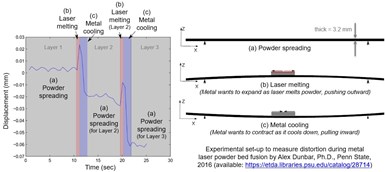
Figure 1. Experimental validation of warping and distortion that results from repeated heating and cooling during metal laser powder bed fusion (adapted from Alex Dunbar, Penn State, 2016)
As many people know now, the warping and distortion results from the residual stresses that accumulate during the build. The constant heating and cooling (i.e., thermal cycling) causes regions in the part to expand and contract (see Figure 1), which induces residual stresses in the metal AM part. The same thing happens during welding, which is why joints are stress-relieved after welding. Again, no surprises here, and while countless methods, tools and algorithms exist to try and avoid overhanging structures when designing a part, supports remain inherent to L-PBF.
Velo3D and now SLM Solutions have fundamentally changed the game though for L-PBF, eliminating the need for supports with their SupportFree and Free Float technology, respectively. This has always been within the realm of the possible; it just required a lot of time and energy (and money) to perfect the algorithms and software needed to analyze every feature on a part, identify the downward facing surfaces on each of these features and compute the appropriate process parameter settings for the laser scan pattern based on the angle of inclination for each surface on each feature of each layer for each part. Piece of cake, right?
Velo3D was among the first AM original equipment manufacturers (OEMs) to offer this, and it was great to see them named as one of Most Innovative Manufacturing Companies in Fast Company—a possible first for an AM OEM to be named on their list. Nonetheless, what I did not fully appreciate until I was speaking with Mike Rogerson last month was how eliminating supports from the majority of metal parts completely changes the economics for manufacturing existing parts, as I have railed against time and again.
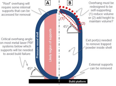
Figure 2. Challenges of making a simple pressure vessel using metal using laser powder bed fusion: original shell (A) as well as redesigned shell (B) to avoid overhangs using one of two possible solutions (1) and (2)
No supports means no scrap. It means no wasted material, no unnecessary build time and not nearly as much post-processing. It also means simpler geometries are easier to make, as well as more complex geometries. Take a pressure vessel, for example. They are relatively simple in terms of shape, but you could never replicate one of these easily with L-PBF processes that require supports, because a portion of the internal shell structure will likely exceed the critical overhang limit (see Figure 2). Redesigning the internal structure of a pressure vessel in order to eliminate overhangs that need supports requires extra engineering effort, time and cost, and it drives up risk—and good luck passing code; code cases for AM pressure vessels are still in development.
So while eliminating supports may sounds like a small thing, it is big for metal AM. It means that process substitution is exactly that—process substitution. Not redesign to make AM work. Thus, companies can spend their time and money qualifying an AM process and the associated material feedstocks, not re-engineering parts, and the uphill battle is no longer as steep.


.png;maxWidth=300;quality=90;format=webp)


Related Content

What is Powder Bed Fusion 3D Printing?
Whether in metal or polymer, with a laser or an electron beam, powder bed fusion (PBF) is one of the most widely used 3D printing techniques.
Read More
3D Printed Cold Plate for an Electric Race Car: The Cool Parts Show #51
An unconventional lattice design and biomimicry are key to the performance of this fluid-cooled heat exchanger for a battery-powered race car.
Read More
World’s Largest Metal 3D Printer Seen at Ingersoll Grand Opening Event
Maker of large additive and subtractive machines adds capacity in Rockford, Illinois.
Read More
3D Printing Molds With Metal Paste: The Mantle Process Explained (Video)
Metal paste is the starting point for a process using 3D printing, CNC shaping and sintering to deliver precise H13 or P20 steel tooling for plastics injection molding. Peter Zelinski talks through the steps of the process in this video filmed with Mantle equipment.
Read MoreRead Next
GE Additive Rebrands as Colibrium Additive
As part of the brand name transition, both the Concept Laser and Arcam EBM legacy brands will be retired.
Read More
Looking to Secure the Supply Chain for Castings? Don't Overlook 3D Printed Sand Cores and Molds
Concerns about casting lead times and costs have many OEMs looking to 3D print parts directly in metal. But don’t overlook the advantages of 3D printed sand cores and molds applied for conventional metal casting, says Humtown leader.
Read More
Video: Intelligent Layering Metal 3D Printing at 3DEO
Contract manufacturer 3DEO delivers metal parts using Intelligent Layering, a binder jetting-like 3D printing process the company developed and operates internally. Here’s how it works.
Read More