
Consider Thickness, Tolerance and Proximity in Laser-Sintered Holes
A study offers guidelines for hole design in laser sintering applications.
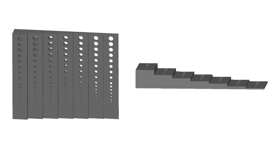
To study thickness and tolerance, the team analyzed a stair-stepped part with hole diameters ranging from 0.125 to 4 mm and wall thickness ranging from 0.939 to 12.7 mm. On the left, the horizontal orientation shows the hole detail, the vertical orientation shows the stair-stepped detail. The larger holes were used to test tolerance.
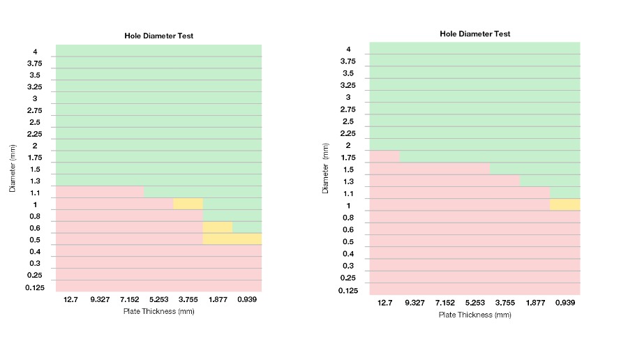
Red means no light was able to pass through the hole – a fail; yellow means the hole resolved but lacks tolerance; green means true accuracy – a pass.
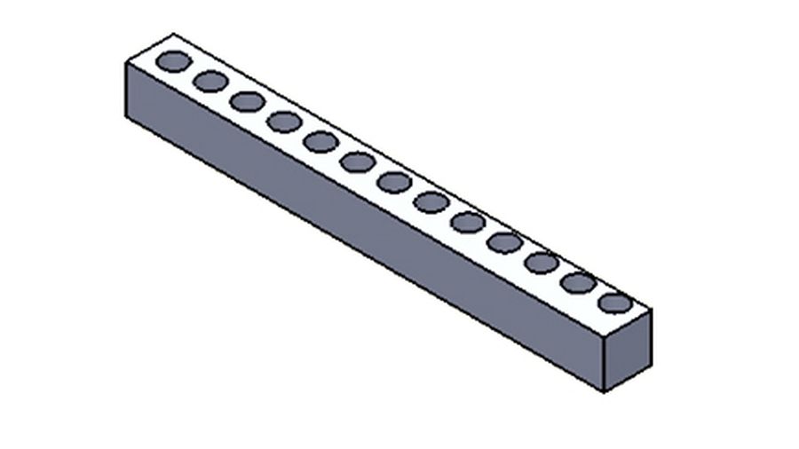
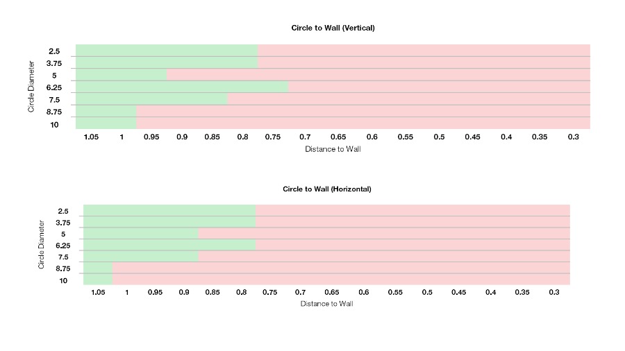
To test hole proximity, the team tested a square shaft. Hole diameter fell between 2.5 and 10 mm, with some placed closer to the edge of the part than others. That distance ranged from 0 to 1.05 mm
Hole accuracy and formation were tested on a pass/fail basis.
Share


3D printing’s innate design capabilities allow holes to be incorporated directly into the part. But that doesn’t mean design engineers can just add holes to designs and call it a day. They first have to determine three key factors in hole design:
- Diameter versus thickness
- Diameter versus tolerance
- The hole’s proximity in regards to other part features
Thickness and Tolerance
A survey led by the University of Texas at Austin with Stratasys Direct Manufacturing tested laser sintering (LS) techniques for the development of design guidelines, including hole formation. The research team designed a part with seven different wall thicknesses and 21 holes sintered into each thickness. The part was built in both a vertical and horizontal orientation. The goal of this test was to determine the design accuracy and hole resolvability in each orientation.


Hole diameter accuracy findings were based on a pass/fail basis. A pass meant the hole was fully resolved with light able to pass through, while a fail meant no light was able to pass through.
Based on the study’s findings, the following is recommended for hole diameter and wall thickness:
- Build holes with a diameter of at least 1.5 mm, as the project allows.
- For best resolvability chances, vertical orientation is better for holes smaller than 1.5 mm.
- Keep surrounding wall thickness at least 3.0 mm thick for better hole accuracy.
Proximity
For hole proximity, the research team tested a square shaft with holes varying both in size and placement. The features within the part were built in either a horizontal or vertical orientation.
The hole accuracy and formation were tested similarly to the first part of the study; the hole either passed or failed with the exemption of a partial hole formation.
The study suggests the following recommendations for hole proximity:
- Design holes with a distance of no less than 0.8 mm to the closest feature, wall or part edge.
- Allow for more space between bigger holes and the closest feature, wall or part edge. Example: A hole diameter of 10 mm requires at least 1.05 mm distance from the nearest feature.
- Orient the hole features vertically. While there were minimal differences in hole resolvability between horizontal and vertical hole orientations, a vertical orientation will provide better wall support.
Related Content
-
ActivArmor Casts and Splints Are Shifting to Point-of-Care 3D Printing
ActivArmor offers individualized, 3D printed casts and splints for various diagnoses. The company is in the process of shifting to point-of-care printing and aims to promote positive healing outcomes and improved hygienics with customized support devices.
-
AM 101: Digital Light Synthesis (DLS)
Digital Light Synthesis (DLS) is the name for Carbon's resin-based 3D printing process. How it works and how it differs from stereolithography.
-
How Large-Format 3D Printing Supports Micro-Scale Hydropower
There is potential hydroelectric power that has never been unlocked because of the difficulty in capturing it. At Cadens, additive manufacturing is the key to customizing micro-scale water turbine systems to generate electricity from smaller dams and waterways.


